Hi Fellow Fanatics!
I'm a new member and this is my first post. I've searched about this here but maybe my search skill was not good enough..
I came across this article on soundstage.com:
http://www.soundstage.com/maxdb/maxdb071998.htm
which basically says that E-I is better than toroid and cheaper.
So, which one is better: E-I or toroid, weight and price consideration aside, only sonic benefit matters? If E-I is really better and cheaper, then why most amps on the market use toroid? (Maybe making 2 chassis and using E-I is more expensive than using toroid in 1 chassis. But that doesn't explain why separate PSU's still use toroids.)
Thanks!
sltgguy
It is important Per ")
For power SS amps that need lots of peak current toroidal transformers are simply the best, provided you take measures for the large peak currents in the leads and power cord (EMC).
But for low current devices like pre amps I stick to “block transformers”, those with an U-shaped core inside. To me this sounds better than toroids.
Cheers
Pjotr said:It is important Per
But for low current devices like pre amps I stick to “block transformers”, those with an U-shaped core inside. To me this sounds better than toroids.
It's a tougher coice for low level devices. The EI core is better for keeping line noise out of the circuit. But an EI core transformer has a lot high stray magnetic field problems which is an issue with low level circuits.
Sheldon
If you decide to go with a E-I type for low-level applications, you may want to consider using a "humbucker" type. They have a bit less radiation than the typical type, and also has the advantage of less capacitance between the windings. A split-bobbin type would also have lower capacitance.
However, if you use it to make a +/- supply, the current draw in each leg will need to be equal, for the radiation field to be low.
Jocko
However, if you use it to make a +/- supply, the current draw in each leg will need to be equal, for the radiation field to be low.
Jocko
I use E-I almost exclusively (mainly for pricing reasons) - but i said it again and i say it before: if you shield you transformer with a conductive strip (Cu or Aluminum sheet an paper do wonders), they radiate so low it's of no consideration. I still do aditional shielding when possible with a Faraday cage, but it's mainly because most of the times i end up with the transformer way too near the circuitery.
Hi,
Meant actually U-I shaped cores in my previous post:
And indeed if you wrap an extra short in the form off copper foil around the transformer stray field is negligible. But in practice I found it not necessary.
Cheers
Meant actually U-I shaped cores in my previous post:
An externally hosted image should be here but it was not working when we last tested it.
An externally hosted image should be here but it was not working when we last tested it.
And indeed if you wrap an extra short in the form off copper foil around the transformer stray field is negligible. But in practice I found it not necessary.
Cheers
stokessd said:
The EI core is better for keeping line noise out of the circuit.
This is true with standard off-the-shelf toroidal transformers, but not necessarily so when you put an interwinding (electrostatic) screen in. Such screens are a must for high-end audio IMO. Sorry to nitpick, but it seems like toroidal TXs get a bad rap unnecessarily, if only because the utility of an interwinding screen is not well known in DIY circles, and not many manufacturers put them in their standard products for cost reasons.
This is true with standard off-the-shelf toroidal transformers, but not necessarily so when you put an interwinding (electrostatic) screen in.
Whilst this is indeed true (the electrostatic shield reduces the effect of the inter-winding capacitance, the primary coupling mechanism for the HF noise) it's nowhere near as effective as a split bobbin EI or C-core.
Copper shielding to an EI transformer isn't as effective as the inherently low radiated field from a toroidal either, but even with toroidals the effect of distancing them from the circuitry they power is clearly audible.
For lower powers an EI core can be more space efficient than a toroid too, for larger powers a toroid makes sense.
There are also techniques, such as that used on some recent toroidal transformers designs, that take the secondary windings and connect them in antiphase at high frequencies, effectively cancelling HF noise, but this isn't very effective with standard toroids, due to the inability to control leakage inductance.
The lack of an air gap to toroids also leaves them very prone to mechanical noise, if there's distortion present on the mains.
Andy.
It seems to me that the main disadvantages to even the cheap toroids is their intolerance to DC and relatively poor noise rejection.
Many DIYers who want to isolate the stray magnetic fields will place transformers in seperate boxes (or a shielded area of the main component), whereas this is less necessary (but not necessarily less practiced) with toroids.
If using a toroid in a component, why not also include a DC blocking circuit and a line filter? Although this could be argued to negate the main advantages of the toroid in the first place - space saving and the ability to place near components.
I guess it's all horses for coarses at the end of the day though - well designed toroids have their place as do well designed EIs.
Shilelded transformers
I have never bothered about shileded transformers before since
they are not readily available, however I now happen to have
two such creatures I bought as surplus. The question then is,
how should the shield be connected?? Does it work to connect
the shield to the secondary side ground (assuming the
transformer is used for a dual-rail supply), ie. the signal ground?
Hi,
Apart from low inter winding capacitance, leakage inductance plays a role in keeping mains noise out. E-I, C and U-I cores have much larger leakage inductance than toroids, especially at lower frequencies. It also makes the transformer “softer” and as such it lowers peak currents in the rectifier. For some leakage inductance you need a leakage magnetic field. And yes in a poor designed transformer this leakage field spreads around the transformer. The task of a copper foil shorting winding around the complete ransformer is to keep the leakage field inside the transformer. This is not only effective at high frequencies (SwMode-PSU’s) but also at 50/60 Hz.
Oh eh Christer, what do you mean by shielding? Are they canned in a steel box or is there an electrostatic shield between pri en sec? Well, in most cases it is connected to the chassis ground.
Cheers
Pjotr said:
Oh eh Christer, what do you mean by shielding? Are they canned in a steel box or is there an electrostatic shield between pri en sec? Well, in most cases it is connected to the chassis ground.
I meant electrostatic shield. I suppose that by chassis ground
you mean the safety ground (earth or whatever) in the wall
outlet, which is the answer I had anticipated. Unfortunately,
that is not an option since we usually do not have that available
in the wall outlets in swedish homes, but just live and neutral.
That is the reason I wondered whether connecting the shield
to signal ground, preferrably at the star ground point, I suppose,
might work too.
Pjotr said:You need to let the noise currents coming from the shield go to the least harmless point. The star ground point is indeed the most suitable point then IMO.
Oops, must be "most harmless point" or "least harmful point"

Pjotr said:
Oops, must be "most harmless point" or "least harmful point"
Don't worry, I read it the way you meant without even noticing
you actually said the opposite. I have a tendency to do such
mistakes too, saying the opposite of what I mean, but mostly
when talking.
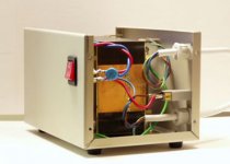
Since there are no torroid manufacturers in Singapore, I have my EI specially wound.
The core I use is Z-11. This is a higher grade core which is used for tube amps in their power and output stages. This laminate is twice the cost of H-14, which is one of the best for industrial applications.
The wires that are used in the windings have enamel coatings that are rated to withstand 200 degress Centigrade max. They are also thick enough to withstand short term short circuit.
Secondary windings are Bi-filar. And to finish it off, the transformer is externally Cu wrapped and finally vacuum impregnated varnish coated for noise free operation.
Attachments
- Status
- This old topic is closed. If you want to reopen this topic, contact a moderator using the "Report Post" button.
- Home
- Design & Build
- Parts
- Transformer: Toroid vs E-I