As usual, with as few turns as possible without saturating the iron. . .
If you were going to design a transformer that completely ignored the bass (let's say below 100 Hz) in favor of optimizing treble, how would you do it?
")
That said, iron size mostly depend of the quantity (volume) of copper you have to wind to keep Joule's losses low.
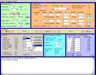
Something like that (quick and dirty) :
(EI54 core size means the I part is 54mm long)
Attachments

The impedance of a primary is equal to the inductance of the primary. To match impedance to a tube you need to add the transconductance and turns forced load line in parallel, then add the DCR of the primary in series. This is the number to use to decide if your transformer will match with a tube at the lowest frequency you care about.
Bud
Hi, Bud! In Russian scientific/engineering books this is called "method of equivalent generators". How it is being referred in English literature?
The original question still stands: is there a standard test frequency for stated transformer inductance ?
Richard
Usually primary inductance is measured at 100Hz/1V, since most LCR meters use fixed voltage - 1V, and 2 fixed frequencies - 100 Hz and 1 KHz.
However, sometimes (e.g. Plitron) lists enormous primary inductance measured at several hundreds V of primary (its peak value).
Please note that primary inductance is noted WITHOUT DC bias, which is always there, even with push-pull output stage (its impossible to fully balance idle current no matter what, small discrepancy will remain). In order to calculate primary inductance with DC BIAS, you will need permeability curves.
My PP output transformer (60W / 5K) I'm currently have primary inductance 88H at 1V/100Hz measured with LCR meter.
kawasaki99, what is your final objective? To test existing transformer or to wind your own with the core you have? If second, you can post dimensions and what would you like to get, I will reply with final data.
In said example the L must be at least 5000/(2pi*20) = 40H
Wow, that's a lot of turns! Any one wonder why I stick to low Rp tubes?
Push-pull amplifiers with low Rp may have very big disadvantage - high sensitivity to phase shift caused by leakage inductance, and as result, oscillation.
In the books I have it is noted that for high Rp tubes (>=3.6K) maximal recommended value of leakage inductance is 20 mH, for low Rp tubes - 7 mH. Indeed, it is not so easy to obtain, especially with EI core.
Additionally, transformers with large core and small number of primary turns may have suboptimal performance on low signal level.
BTW, 40H for 5K transformer is a way too low. Small discrepancy of output tubes idle current (which is always there) will magnetize core and drop inductance. There are not so many ways to cure this. Lundahl, for example, uses micro air gap.
Last edited:
Sy, what tube / power level are you interested in? For less than 5 watts I would suggest 48% nickle core. For 5 to 25 watts 1" center leg M3 core. For high frequency optimization you want a core that allows a fast rise time for the planar fields created by the antenna event between primary and secondary. The M3 will sound very much like the 48% nickle.
As for oscillation in the core, just DO NOT stack the core like a power transformer core. Treat it as if you were going to make a three section distributed gap. Meaning three large chunks of core. This will provide enough of a gap to allow 10 ma of DC current to flow, without any detriment to the core. This will also provide you with passive demagnetization, the holy grail of audio transformer design, no remnant polar magnetic field, hanging on until zero voltage.
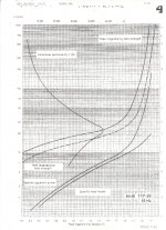
Plitron and others reporting massive inductance, are using the AC permeability curves. You can take the DC perm curves and multiply the max values by 4 to obtain AC perm curves. I have attached perm curves for all E/I core and both nickle E/I cores, along with a very informative curve for AC perm for M6 core material. Note where on the "Amplitude Permeability" curve the maximum perm occurs and what happens below that point. This AC permeability is only available for 1/2 of an RMS wave form or a transient peak. It is the characteristic used to generate pulsed high voltages, the inhibitor to keep the bulls from strolling down that hill and taking care of all of the girls. The E/I curves are for core with DC flowing and as Links points out, DC flows always, even in SS amps driving a PP OPT.
As for oscillation in the core, just DO NOT stack the core like a power transformer core. Treat it as if you were going to make a three section distributed gap. Meaning three large chunks of core. This will provide enough of a gap to allow 10 ma of DC current to flow, without any detriment to the core. This will also provide you with passive demagnetization, the holy grail of audio transformer design, no remnant polar magnetic field, hanging on until zero voltage.
Plitron and others reporting massive inductance, are using the AC permeability curves. You can take the DC perm curves and multiply the max values by 4 to obtain AC perm curves. I have attached perm curves for all E/I core and both nickle E/I cores, along with a very informative curve for AC perm for M6 core material. Note where on the "Amplitude Permeability" curve the maximum perm occurs and what happens below that point. This AC permeability is only available for 1/2 of an RMS wave form or a transient peak. It is the characteristic used to generate pulsed high voltages, the inhibitor to keep the bulls from strolling down that hill and taking care of all of the girls. The E/I curves are for core with DC flowing and as Links points out, DC flows always, even in SS amps driving a PP OPT.
Attachments
Last edited:
Bud, what got me thinking was that so many tube guys have setups like mine, where the tube portion never really handles bass (I have some Sunfire amps for that). Anyone with subwoofed mini-monitors, for example.
So... let's look at something like 6L6GC or parallel EL84 in AB2 triode. 25-30 watts nominal. What can be gained by ignoring the bass?
So... let's look at something like 6L6GC or parallel EL84 in AB2 triode. 25-30 watts nominal. What can be gained by ignoring the bass?
SY,
Why do you ask Bud the same question as so well answered by Yves in post 21??
The discussion is heading in the direction of what makes a good transformer, and what I miss is the influence of dc resistances and core geometry.
Compare two "identical" output transformers with identical cores, same number of windings a.s.o, but different wire diameters, resulting in the first transformer having a primary dc resistance of 120 ohms, secondary dc resistance of 0,3 ohms. The second transformer has 60 ohms primary dc resistance and 0,1 ohms secondary dc resistance.
Inductance is the same as the the cores and numbers of windings are the same. Winding capacities might be different but that is not the point now.
Compare both transformers sonically and let me know what sounds better.
Another point is core geometry.
I understand that companies like Hammond, Edcor and others use Ei cores for economic reasons. But why do some quality winders still stick to EI cores, whereas c-cores have better properties to begin with? Tango, Tamura, the higher quality range of Audionote, European winders like Bartolucci and myself apply c-cores exclusively. Toroidal cores have even better properties but have winding difficulties in my opinion.
For instance: McIntosh used c-core output transformers in the good old days; nowadays MC275 uses crap EI core transformers apparently for economic reasons. I don't understand it; the cost of a good quality c-core is not much higher than EI laminates, and pretty irrelevant because labour (winding; finishing) dominate the total cost of the transformer.
SY,
Why do you ask Bud the same question as so well answered by Yves in post 21??
I'll even ask you the same question, since you also make extremely well-regarded transformers.
There's art and creativity in OPT design; when freed of a major constraint, it is interesting to me to see how different people whose abilities with iron I trust approach the problem. Can this allow a breakthrough by dropping design paradigms based on bass?On a selfish level, this is something I'm interested in building, and most of my design decisions will be by what the OPT designer comes up with.
A well designed (output) transformer has enough primary inductance to give sufficient and undistorted bass output and the coil must be wound in order to give good coupling from primary to secondary, at the same time minimizing capacities in order to give good HF bandwidth.
In the case of the single ended output transformer (actually all output transformers) the challenge is to find a good balance between undistorted bass and good HF bandwidth. Shifting the balance towards the bass will impair HF bandwidth vice versa.
Low Rp tubes like 2A3, 300B and trioded KT88 make things simpler, but in the case of 45's and most transmitting tubes with Rp's in the order of 1k5 and higher there is a real challenge.
Cutting the bass make things much easier. When the tube amp is relieved from bass duty the balance of the output transformer can be shifted towards HF. However I would never use the bass drop of the transformer (caused by lack of inductance) to determine the high pass function as "lack of inductance" is also close to core saturation. I'd like the transformer to have enough inductance at about two octaves below the cut off point.
On the other hand, the dedicated bass tube amp can have an output transformer with high inductance and low dc resistances in the windings to guarantee undistorted bass and optimal damping.
It is not a breakthrough approach; I did it several times.
However I would never use the bass drop of the transformer (caused by lack of inductance) to determine the high pass function as "lack of inductance" is also close to core saturation. I'd like the transformer to have enough inductance at about two octaves below the cut off point.
No argument there. A nice high slope electronic crossover should be part of any biamped system of this sort.
A nice high slope electronic crossover
Once you have your Jan/Berringer up and running and have chosen the final appropriate slope for the driver you are interested in, using a wide range transformer, I am sure any of us can provide an optimized design using our personal choice of the available materials. Keeping in mind that the transformer will be adding to that slope and that the -0.1 db point must be chosen with care, assuming that the core is still functional for power transform at that frequency.
At the top level of magnetic performance what type of core you use is just a personal choice, based upon other parameters of interest. Above 400 Hz the difference between one core format and another is trivial, unless the core chosen requires that capacitive coupling be crippled to ensure flat frequency response beyond 20 kHz. Below 400 Hz all forms of core introduce their own particular design challenges. Some of the solutions are not intuitive, nor mathematically derived and so an individual designer will choose to limit what he has to learn on his own to achieve parity in performance with other designers, who have concentrated their efforts in other directions.
Another point is core geometry.
I understand that companies like Hammond, Edcor and others use Ei cores for economic reasons. But why do some quality winders still stick to EI cores, whereas c-cores have better properties to begin with? Tango, Tamura, the higher quality range of Audionote, European winders like Bartolucci and myself apply c-cores exclusively. Toroidal cores have even better properties but have winding difficulties in my opinion.
100% correct. The problem is that EI cores are in relatively good supply, whereas double-C cores of required material and dimensions are not. It is not a problem to make any double C-core of whatever material and size, and corresponding bobbin, but most factories require very large MOQ (minimum order quantity), usually 500 - 1000 pcs or 1 tonn. And one Japanese company (when I inquired them) informed that they are not interested in orders less then $140,000.
So companies like Lundahl, which have their own machinery to build any double C-core, have very big advantage over the rest of crowd.
Toroidal cores have even better properties but have winding difficulties in my opinion.
In fact, standard toroid cores (all manufacturers size them in close pattern) are badly suited for winding audio output transformers. Take for example Plitron. Why do they have standard output impedance 5 Ohm only even in professional, very expensive models, costing 300+ EURO each? Answer is damn simple. "Standard" toroid cores are made for relatively low number of turns and small number of winding layers. I have a program which simulates winding toroid - with "standard" off the shelf toroid core simply impossible to have universal well designed transformer, it must have either only single output impedance either be as large as behemoth. And contrary to widely accepted belief audio toroids must have primary/secondary interleaves!
The problem is that EI cores are in relatively good supply, whereas double-C cores of required material and dimensions are not. It is not a problem to make any double C-core of whatever material and size, and corresponding bobbin, but most factories require very large MOQ (minimum order quantity), usually 500 - 1000 pcs or 1 tonn. And one Japanese company (when I inquired them) informed that they are not interested in orders less then $140,000.
So companies like Lundahl, which have their own machinery to build any double C-core, have very big advantage over the rest of crowd.
I run a one man company, and I have no trouble in finding c-cores in the appropriate numbers and grades. Maybe I pay a bit more because of the smaller quantities but as pointed out earlier the cost of labour in winding transformers are dominant anyway.
There are also "Long E" laminations available. Thomas and Skinner have a selection. I think it was AcroSound that used these type famously. They typically will accept two standard bobbins end to end on one tongue conveniently. Great for dual sectioning. Or you can fit two dual bobbins for quad sectioning. These will get you low magnetizing current (below saturation) like a toroid or cut core, since most of the magnetic path length is grain oriented properly, and low leakage L due to the long thin windings like a toroid. The "high end" practice of selling scrapless EI lams with silver windings is beyond belief to me, like selling quitar amplifier OTs with gold cases.
------------
"And contrary to widely accepted belief audio toroids must have primary/secondary interleaves! "
Are you counting a full center tapped P-P winding as a single winding here? (assuming progressive wind technique of course). This would indeed have bad coupling with only half the circumference active at a time in class AB. Each plate half winding requires a full wrap of the core for low leakage L. I have a simple two layer (isolated secondary) GE Variac core here which I have measured, and it has fabulous low leakage coupling compared to any audio OT I have seen. 0.58 mH (of course this is for the limited turns for 120V at 60 Hz, but then it also uses a thick, 1/8 inch, molded insulation sleeve between the windings, an audio OT would have just a thin mylar wrap).
I would expect that each plate winding side of a CT'd P-P toroid primary would need its own progressive wind layer around the full core circumference, and one might additionally swap inner to outer at the half way point to get equal winding resistances for the two plate sides. Of course it would certainly be best if the secondary layer were layered in between the two primary layers. I would be more than happy to get similar leakage L as the Variac without any extra interleaves.
Last edited:
"And contrary to widely accepted belief audio toroids must have primary/secondary interleaves! "
Are you counting a full center tapped P-P winding as a single winding here? (assuming progressive wind technique of course). This would indeed have bad coupling with only half the circumference active at a time in class AB. Each plate half winding requires a full wrap of the core for low leakage L. I have a simple two layer (isolated secondary) GE Variac core here which I have measured, and it has fabulous low leakage coupling compared to any audio OT I have seen. 0.58 mH (of course this is for the limited turns for 120V at 60 Hz, but then it also uses a thick, 1/8 inch, molded insulation sleeve between the windings, an audio OT would have just a thin mylar wrap).
Hmmm, I did not get your point entirely. Audio transformer primary have several thousands of primary turns, so even each half of primary (plate end <-> center tap / center tap <-> plate end) will occupy several layers. As for your concern for small discrepancy of DC resistance of two primary halves, it is so small compared to primary impedance that it doesn't matter (e.g. 20 Ohms compared to 5K). I heard someone in Russia made audio toroids with balanced winding, but IMHO it is an overkill good only for marketing and profiting purposes. From the technical perspective it is extra build complexity for no gain whatsoever.
I run a one man company, and I have no trouble in finding c-cores in the appropriate numbers and grades. Maybe I pay a bit more because of the smaller quantities but as pointed out earlier the cost of labour in winding transformers are dominant anyway.
Hi, Peter! Have you sourced GOSS Hi-B double C cores?
- Status
- This old topic is closed. If you want to reopen this topic, contact a moderator using the "Report Post" button.
- Home
- Amplifiers
- Tubes / Valves
- Output Audio Transformer Impedance