If you will look at Fig. 1 of my IEEE paper, you will find a line that shows the PEAK waveform envelope of the TIM(30,30) waveform that I developed at VTT in Finland. To reproduce this spectrum, you have to take a 3.18KHz square wave, bandwidth limit it with a single pole rolloff at 30 KHz, then go though an INVERSE RIAA NETWORK that flattens out at 30KHz in its boost. The TIME RESPONSE of this waveform is in the paper. Please note how it resembles the TIME RESPONSE of the 32 year old Ortofon MC cartridge.
It is important to compare Fig. 7 to Fig. 8, carefully noting that the graphs are NOT EQUAL in time duration. One is 5uS/div. The other is 10uS/div. IF you take this into consideration, the two pulses are VERY SIMILAR in duration and overall shape.
Therefore, you must pass a TIM(30,30) waveform, AND you will get a 10us risetime square wave at the output of the preamp. I have measured this with real phono preamps. Please note that it is NOT a triangular wave. Now, have MC phono cartridges gotten slower than they were 32 years ago? I think not, so maybe this is a good place to start.
Therefore, you must pass a TIM(30,30) waveform, AND you will get a 10us risetime square wave at the output of the preamp. I have measured this with real phono preamps. Please note that it is NOT a triangular wave. Now, have MC phono cartridges gotten slower than they were 32 years ago? I think not, so maybe this is a good place to start.
For the reason that we speak about faster signals (not very fast yet), opamps and feedback, I would like to demonstrate a more demanding signal, than MC output.
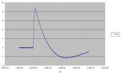
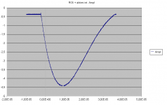
The amplifier input signal is from Rogowski Coil, measuring 8/20 us high impulse current of several kA in a High-Voltage test lab setup, with plenty of interference.
The output signal is from inverting opamp integrator. This integrator consists of very fast opamp and very fast buffer.
As we can see, the input signal, which is derivative of measured current, has sub-microsecond rise time. Output of the opamp integrator properly displays the shape of measured current. Now please understand why I become nervous when I hear that 5 - 10us of input risetime generally makes problems to feedback circuits.
Attachments
Now, if you have gotten this far, we as still back to 22 years ago. It is relatively to talk about the past, because it is less subtle than present changes to make a better phono stage, and first, we should go back and see WHY what I 'evolved' to over 15 years of solid state phono design really did work better.
To understand this we need to know more about the dynamic performance of moving coil phono cartridges. To get a visual 'handle' on this, we have to go back to my 1978 IEEE paper, "Omitted Factors in Audio Design' linked here, somewhere. To do this paper, I had to look at the REAL BANDWIDTH of a MC phono cartridge, especially when mistracking, which it does a good deal of the time. You will find, if you do this, with the right test equipment that requires transient storage and response at least to 1 Meg Hz, that phono cartridges can 'spit' garbage out to 500KHz, and 200KHz being typical. This is HARD on many feedback amplifiers. Why is this often overlooked? Well, the phono stage essentially INTEGRATES the input signal and tames it down, so to speak, but that does not imply that the INPUT STAGE is very happy doing it. Also, ticks and pops put out a tremendous transient that will virtually overload any input stage, so you had better be able to recover virtually instantly, or the tick or pop will be extended in duration and more audible. This is part of what many inexpensive phono playback systems suffer, and cause so much complaint. More later.
John
nice post thanks. Like I mentioned in an earlier post your brain can add the musical structure even if it's in the lowest amplitude or not reproduced...
Yes, PMA, your output looks OK, BUT you are using an INVERTING integrator. A phono stage is a NON-INVERTING integrator, with the input filter set at 30KHz, rather than 1 Hz or so. Please note the difference. Then look at Graph 1 which shows the TIM waveform with the LF356, an early jfet input op amp. Is .03% to 0.1% OK?
Going further Pavel, I suspect that your INVERTING INTEGRATOR never sees the transient in the first graph that you presented, only the second graph, and THAT is only 1/2 as fast as the TIM(30,30) waveform that I used. This is because the input signal is ALREADY integrated at the input, due to either inductive or capacitive integration, whichever is used for your INVERTING INTEGRATOR. A practical phono stage, that is normally used, by virtually everybody, is the rough equivalent to a NON-INVERTING integrator and the original waveform appears at the input of the op-amp. This is the problem. So where you think that you are handling a faster signal, you are really handling a slower signal by approximately 2 times, and using a very fast IC op amp as well. Still, how do you know how much REAL distortion you are generating? How accurate do you have to be? 1%, .1%, .01% ?
Manly thing to do in my opinion is to post pictures of the phono stage response
As john said this is 5KHz square wave with the 10 us rise time.
I supose both your phono stages can do this?
PMA
sorry but the 2 graphs don't do much to me vertical scale on first one is 2 times scale on second
A MC phono stage has gain of 60dB normaly
As john said this is 5KHz square wave with the 10 us rise time.
I supose both your phono stages can do this?
PMA
sorry but the 2 graphs don't do much to me vertical scale on first one is 2 times scale on second
A MC phono stage has gain of 60dB normaly
PMA
sorry but the 2 graphs don't do much to me vertical scale on first one is 2 times scale on second
Sorry, second graph is -integral of the first, so you have to know integrating constant to calculate exact voltage value. This constant is not important, the shape is important. In case you understand how to integrate and differentiate, then you can easily compare the two images. Multiplication constant is not important to do this.
Yes, PMA, your output looks OK, BUT you are using an INVERTING integrator. A phono stage is a NON-INVERTING integrator, with the input filter set at 30KHz, rather than 1 Hz or so. Please note the difference. Then look at Graph 1 which shows the TIM waveform with the LF356, an early jfet input op amp. Is .03% to 0.1% OK?
LF356 is not OK.
John, have you noted my recommendation of the ADA4898-1 (or 4898-2, double). I am sure Scott might support you with samples.
ADA4898-1 | High Voltage, Low Noise, Low Distortion, Unity Gain Stable, High Speed Op Amp | Operational Amplifiers (Op Amps) | Amplifiers and Comparators | Analog Devices
http://www.analog.com/static/imported-files/data_sheets/ADA4898-1.pdf
0.9nV/rtHz, 55V/us, GBW = 65MHz, unity gain stable, 8mA PSU current.
Last edited:
Yes, PMA, your output looks OK, BUT you are using an INVERTING integrator.
Good point, John!!
Yes, the non-inverting integrator would not work in my measuring instrument. The complete instrument is in fact non-inverting, as it has inverting output stage, and (-) x (-) makes (+). I have shown only images from development stage of the integrator, it was measured in 2003.
Going further Pavel, I suspect that your INVERTING INTEGRATOR never sees the transient in the first graph that you presented, only the second graph, and THAT is only 1/2 as fast as the TIM(30,30) waveform that I used. This is because the input signal is ALREADY integrated at the input, due to either inductive or capacitive integration, whichever is used for your INVERTING INTEGRATOR.
I would respectfully disagree. To respond properly, the active integrator must create accurate output to keep virtual ground at zero level. If not, then the output signal is distorted and not an exact integral anymore. So, in case the integrator is not a) fast enough b) cannot provide transient current to charge feedback capacitor, then the output is incorrect.
PMA said:I would respectfully disagree. To respond properly, the active integrator must create accurate output to keep virtual ground at zero level. If not, then the output signal is distorted and not an exact integral anymore. So, in case the integrator is not a) fast enough b) cannot provide transient current to charge feedback capacitor, then the output is incorrect.
The output never is exact, cause all op-amps, even fast ones have distortion. I don't think you can talk about op amps, even fast ones, in ideal terms. They aren't ideal op amps.
Depends on degree of error, otherwise your statement is pointless, especially that about opamps - just the harvest of anti opamp campaign. Would you rather get better result in open-loop? We have the data in files (the images are data from LeCroy memory) and we can calculate the error.
Back to John's reasoning - the output current of inverting integrator must be an exact copy of input voltage divided by input resistor. Any deviation is an error signal.
Back to John's reasoning - the output current of inverting integrator must be an exact copy of input voltage divided by input resistor. Any deviation is an error signal.
The output never is exact, cause all op-amps, even fast ones have distortion. I don't think you can talk about op amps, even fast ones, in ideal terms. They aren't ideal op amps.
Indeed, though also there isn't any ideal amp. I believe that the main issue here is how can we get as close as possible to ideal amplification, especially in phono stages.
Bks, what IS, IS. This garbage is being generated by phono cartridge mistracking all the time. That is WHY it has to be considered. Would you like to drive a car that almost fell apart when it hit a pothole? The roadbuilders did not make the pothole, but they are out there, and your automobile had better handle it well. Same with phono stages, they must handle mistracking cartridges. If they don't, sound quality will suffer, just like PMA seems to complain about. '-)
I don't think the analogy is valid. You can steer around the potholes, but your phono amp has no choice but to faihfully reproduce the phono distortion. Or cover up the distortion and loose part of the music. A rock and a hard place.
jan didden
PMA said:Depends on degree of error, otherwise your statement is pointless, especially that about opamps - just the harvest of anti opamp campaign. Would you rather get better result in open-loop? We have the data in files (the images are data from LeCroy memory) and we can calculate the error.
But, op amps have lower slew rate!!!
")
I tend to agree with JC ... I'd prefer open loop at the input stage. So the transients are small, but you also need lots of gain in a phono preamp. I just think it might lead to unpleasant types of distortion. Do you use less gain on the input stage and then add more opamps for gain? Could sound bad.
Pavel, I am NOT criticizing your solution, TODAY! But the BEST OP AMP for the job, the LF356, when I did the measurements, had plenty of distortion.
To understand the integration that you are doing better, which TYPE of integration are you doing? Are you using RC or LR? (at the input, of course)
To understand the integration that you are doing better, which TYPE of integration are you doing? Are you using RC or LR? (at the input, of course)
But, op amps have lower slew rate!!!
I do not intend to argue with amateurs. You may make a choice of the opamp with 2kV/us Slew Rate. Many of you are blinded by marketing-oriented, non-scientific reasoning. Obviously it works very well.
- Status
- Not open for further replies.
- Home
- Member Areas
- The Lounge
- John Curl's Blowtorch preamplifier part II