Another resistor option is Ohmite Audio Gold non-magnetic, non-inductive 5W axial AG5NGR22E 0,22R/5W 2%.
http://www.hifituning24.de/hifi-tuning/audio-widerstaende/ohmite-audio-gold-non-magnetic/index.php
http://www.hifituning24.de/hifi-tuning/audio-widerstaende/ohmite-audio-gold-non-magnetic/index.php
Matching is compulsary for a balanced amp.
Or it is not balanced.
Rather to build a regular F5 with them.
An N channel and a P channel typically deal with the different halves of the sine wave and I believe these can never really be matched correctly. In a balanced amp with unmatched parts, will it be any different? My understanding is that matching is more for current sharing and dc ofset, but they are not sharing current in this config and Im not sure how much offset I would need to deal with.
Look at post 49.
Matching reduces distortion. Which
is the target.
http://www.diyaudio.com/forums/pass-labs/121228-f5-power-amplifier-884.html#post2293745
Matching reduces distortion. Which
is the target.
http://www.diyaudio.com/forums/pass-labs/121228-f5-power-amplifier-884.html#post2293745
Last edited:
PS.
bobodioulasso
Tanks for the links to the jucy bits.
When I get a chance I will collate the lot.
Thus making the 900 page original tread usefull.
Al
Bobodioulasso or Bksabath, could one of you post this guide to the "Juicy bits"?
Thanks,
russsellc
Gentlemen,
I proposed a resistor for you which IMHO is good value for money and very good sonically. Just look at what they use in high end Japanese amps. If you want to use more fancy resistors, then you can try Isabellehuette PBH, Caddock MP930, Texas Components T220Z, ....... Plenty of choices. The PCB will have 9mm & 5mm pitch, for MPC74 (faithful to my original design) and any TO220 boutique resistors.
If you don't want to GB MPC74, it is just fine with me. I am just thinking ahead for those who want to build it exactly as I did mine.
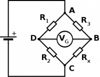
As to resistor matching, this is how I do it myself (see attachment). But feel free to do it your way.
I'll still do the following as promised :
1) get a Gerber for my PCB layout done and send it to Variac, with standard DIYA mounting hole patterns,
2) give guidance and help to AR2 to build his prototype according to the way that I built mine.
He has the generosity to then share his building experience with you, and help those out who is new to the game.
What I will not do is to answer question like "what if I chance your circuit by this and that for xyz special application", ......, etc. I have not tried any other configurations than those I am going to publish, so I have no idea whether your proposed changes will work or not. I can only encourage to experiment and report back your experience. It is not so bad to burn a few transistors -- all part of the education.
")
So now I need to get the layout updated for Variac to check and agree, then Bksabath will get the ACAD files to convert to Gerber, according to my instructions.
That'll be it for tonight,
Patrick
PS My source says MPC74 +/-5%. I have no problems getting quad sets to much less than 0.5% for a batch of 40.
.
I proposed a resistor for you which IMHO is good value for money and very good sonically. Just look at what they use in high end Japanese amps. If you want to use more fancy resistors, then you can try Isabellehuette PBH, Caddock MP930, Texas Components T220Z, ....... Plenty of choices. The PCB will have 9mm & 5mm pitch, for MPC74 (faithful to my original design) and any TO220 boutique resistors.
If you don't want to GB MPC74, it is just fine with me. I am just thinking ahead for those who want to build it exactly as I did mine.
As to resistor matching, this is how I do it myself (see attachment). But feel free to do it your way.
I'll still do the following as promised :
1) get a Gerber for my PCB layout done and send it to Variac, with standard DIYA mounting hole patterns,
2) give guidance and help to AR2 to build his prototype according to the way that I built mine.
He has the generosity to then share his building experience with you, and help those out who is new to the game.
What I will not do is to answer question like "what if I chance your circuit by this and that for xyz special application", ......, etc. I have not tried any other configurations than those I am going to publish, so I have no idea whether your proposed changes will work or not. I can only encourage to experiment and report back your experience. It is not so bad to burn a few transistors -- all part of the education.
So now I need to get the layout updated for Variac to check and agree, then Bksabath will get the ACAD files to convert to Gerber, according to my instructions.
That'll be it for tonight,
Patrick
PS My source says MPC74 +/-5%. I have no problems getting quad sets to much less than 0.5% for a batch of 40.
.
Attachments
Last edited:
Bobodioulasso or Bksabath, could one of you post this guide to the "Juicy bits"?
Thanks,
russsellc
Do not know exactly, i think post 48, 49,...
... Does this increase gain, or does that remain at 15 db? (Of course I mean with the standard feedback resistors)
Russellc
balanced gain is doubled (+6db)
Incorrect. The balanced input signal is still being amplified by a factor of 6.
You do get higher output voltage level at your speakers, but this is not because the gain is higher.
It is because the input signal (= Vin+ - Vin-) is now 2x that of a single ended signal (e.g. Vin+ alone).
Patrick
You do get higher output voltage level at your speakers, but this is not because the gain is higher.
It is because the input signal (= Vin+ - Vin-) is now 2x that of a single ended signal (e.g. Vin+ alone).
Patrick
Last edited:
I thought I would bring this up because some people might be frightened off to build this.
I agree the N devices need to be matched to each other and the P devices need to be matched to each other. However I don't think it is absolutely critical to get perfect matching between N and P. If that was the case Nelson would not use IRFP devices which are not perfect complementary devices to start with.
Even the Toshibas which are better are still not perfect complementary devices.
So could either Papa/Patrick/Juma/Zenstar, comment about how critical all of this is.
This project should be about encouraging people to participate in it, rather than scaring people away.
It would be nice to put things into perspective for people, rather than just saying you need perfect matching.
current matching between all input jfets is a must ;
EUVL's combined source resistor/different Idss - as tricky bonus , for fun and builder's pride
current matching of same polarity of outputs is a must
current matching between polarity of outputs is splitting a hair , but can be fun if you like it
using THD meter and Papa's trick of additional source resistor in appropriate place in output is a cherry on top of cream pie ( and poke in the eye of our usual overengineering .... and above hair splitting )
)
but - some people don't care for cherry , especially not 2000 .

btw. - did I told you that I don't care which mosfets are in output ?
I like it lush
EUVL's combined source resistor/different Idss - as tricky bonus , for fun and builder's pride
current matching of same polarity of outputs is a must
current matching between polarity of outputs is splitting a hair , but can be fun if you like it
using THD meter and Papa's trick of additional source resistor in appropriate place in output is a cherry on top of cream pie ( and poke in the eye of our usual overengineering .... and above hair splitting
)but - some people don't care for cherry , especially not 2000 .
btw. - did I told you that I don't care which mosfets are in output ?
I like it lush
Last edited:
See F5 post
http://www.diyaudio.com/forums/pass-labs/121228-f5-power-amplifier-68.html#post1507044
These toshibas are nice complements.
It's tempting to match them..
http://www.diyaudio.com/forums/pass-labs/121228-f5-power-amplifier-68.html#post1507044
These toshibas are nice complements.
It's tempting to match them..
Last edited:
THD meter does not tell you the whole story.
You need to watch the distribution of 2nd, 3rd, 4th, ...., up to 7th harmonics.
Read the Blowtorch thread.
The rest I already explained here :
http://www.diyaudio.com/forums/pass-labs/121228-f5-power-amplifier-177.html#post2293745
Patrick
You need to watch the distribution of 2nd, 3rd, 4th, ...., up to 7th harmonics.
Read the Blowtorch thread.
The rest I already explained here :
http://www.diyaudio.com/forums/pass-labs/121228-f5-power-amplifier-177.html#post2293745
Patrick
- Status
- This old topic is closed. If you want to reopen this topic, contact a moderator using the "Report Post" button.
- Home
- Amplifiers
- Pass Labs
- Balanced F5 question