Getting a lot of PM's about the boards. They have been mailed to the shipper who is linked to our store. Now they have to log them in and we have to list them on the store..Progress is being made!
Mark
Thank you Mark and Christian!
Of course Papa too.....
")
Ron
Getting a lot of PM's about the boards. They have been mailed to the shipper who is linked to our store. Now they have to log them in and we have to list them on the store..Progress is being made!
Mark
I see the store is not accessible, guess this means its being updated for the F5?
Chad
How hot R11 & R12?
Hi,
Thanks for all the help, I am enjoying my F5 build.
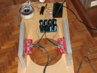
One thing that concerns me is that the R11 and R12 3W resistors are getting fairly hot. The Bias voltage is fairly stable at around 550mv across these resistors. No problem. Is there any danger that the resistors will reduce their resistance due to heat and have a "runaway" effect on the bias current?
Is this normal or should I change the resistors to a 5W wire wound to better tolerate the heat? As far as the sound of the amp is concerned, it is terrific.I have completed reading upto 670 pages of F5 postings. I do not remember the R11 and R12 heat discussion.
BTW, here are the pictures I promised earlier. I am now in the process of getting the chassis fabricated. Once that is done, I will move the F5 into it's new home.
Cheers.
Anil
Hi,
Thanks for all the help, I am enjoying my F5 build.
One thing that concerns me is that the R11 and R12 3W resistors are getting fairly hot. The Bias voltage is fairly stable at around 550mv across these resistors. No problem. Is there any danger that the resistors will reduce their resistance due to heat and have a "runaway" effect on the bias current?
Is this normal or should I change the resistors to a 5W wire wound to better tolerate the heat? As far as the sound of the amp is concerned, it is terrific.I have completed reading upto 670 pages of F5 postings. I do not remember the R11 and R12 heat discussion.
BTW, here are the pictures I promised earlier. I am now in the process of getting the chassis fabricated. Once that is done, I will move the F5 into it's new home.
Cheers.
Anil
Attachments
Hi,
what is the resistance value of R11/12 that you are using?
They should only dissipate ~650mW at quiescent.
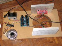
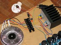
Your main sinks will run cooler if you orient the fins to vertical.
The sink for the two bridge rectifiers is far too big. It will run cold, when as big as that.
what is the resistance value of R11/12 that you are using?
They should only dissipate ~650mW at quiescent.
Your main sinks will run cooler if you orient the fins to vertical.
The sink for the two bridge rectifiers is far too big. It will run cold, when as big as that.
Hi,
what is the resistance value of R11/12 that you are using?
They should only dissipate ~650mW at quiescent.
Your main sinks will run cooler if you orient the fins to vertical.
The sink for the two bridge rectifiers is far too big. It will run cold, when as big as that.
Andrew,
The value of R11/R12 is 0.47ohms, 3 Watt. I suspect the resistors are not actually 3W but could be 2W. They are getting hot enough but maintaining the heat and not burning. The across the resistors is fairly stable at around 550mv.
In the chassis that I am getting built, the heatsinks are aligned vertically to dissipate more heat. Right now the test heatsinks are kept horizontally, as they don't stand vertically.
I am planning to mount the bridge rectifiers to the chassis and not use the heatsink shown in the picture. I am using that again as a part of the test setup, as I am worried that unmounted rectifiers could cause havoc.
Thanks for the advice.
Cheers.
Anil
Hi,
The sink for the two bridge rectifiers is far too big. It will run cold, when as big as that.
I didn't think you could have too much heat sink?
Anil: I use the Ohmites in Jack's kit and they run around 50 degrees, which is pretty hot to touch but well within reason. I would say they are safe till about 70 degrees, which would be enough to burn your finger but it would still be fine for the resistor.
I use a small TO-220 heatsink stuck with thermal tape on the flat side of the resistors.
I use a small TO-220 heatsink stuck with thermal tape on the flat side of the resistors.
Anil: perhaps it's a bit late now, but R11 and R12 should be mounted with some clearance from the pcb. I haven't seen experienced any failure with a very large variety of 3W resistors here -- Panasonic, Ohmite, Caddock etc.
Thanks. It's not late. I can desolder and increase the clearance from the PCB. Meanwhile I will see if I can get some branded resistors like the ones you mentioned.
Anil: I use the Ohmites in Jack's kit and they run around 50 degrees, which is pretty hot to touch but well within reason. I would say they are safe till about 70 degrees, which would be enough to burn your finger but it would still be fine for the resistor.
I use a small TO-220 heatsink stuck with thermal tape on the flat side of the resistors.
Sangram: Thanks. I realized that these resistors do get hot, but are still OK and perform well. I was initially concerned. I ran the amp in idle for 2 hours and then with music for 2 hours. The bias was pretty steady and no problem with the resistors. The heatsinks were pretty hot, I can touch it for around 3-4 seconds.
I will try and get some branded resistors and mount them with some clearance. I got hold of some 0.1 ohms, 3watt Dales in Bangalore. Does it make sense to parallel them and use?
Cheers.
Series you mean, parallel will drop the resistance even more Yes, you could. I would use a temperature meter of some kind to check exactly how hot they get. Bangalore ambient is kinder to Class A electronics than over here.
I worry about your main heatsinks though, I feel they are really very small, the cooler weather notwithstanding. I hadn't seen them before and I hope you have better ones in the main case. These ones will be much better with a slow and quiet fan.
Good Luck
Yes, you could. I would use a temperature meter of some kind to check exactly how hot they get. Bangalore ambient is kinder to Class A electronics than over here.I worry about your main heatsinks though, I feel they are really very small, the cooler weather notwithstanding. I hadn't seen them before and I hope you have better ones in the main case. These ones will be much better with a slow and quiet fan.
Good Luck
Series you mean, parallel will drop the resistance even more
I worry about your main heatsinks though, I feel they are really very small, the cooler weather notwithstanding. I hadn't seen them before and I hope you have better ones in the main case. These ones will be much better with a slow and quiet fan.
Good Luck
My bad. I mean series for the resistors. I am still in capacitance mode
The heatsinks are fairly large. In my chassis, I am going to increase the size and also mount them vertically. I will use a fan if there is no other option. I have access to lot of high quality and quite computer fans.
That looks typical of a choke input filter.
the voltage holds well over the current range from 2A to 5A.
But as the current demand falls below 2A the voltage presented to the amplifier rises to eventually reach 1.4 * Vac (offload), whereas the on load voltage is ~0.9 * Vac(on load).
the range of current that a choke input filter can supply and hold close regulation on the voltage is quite narrow.
As the current demand falls the required Inductance rises.
Double your choke Henries and plot out that 100mA to 5200mA graph.
ClassA amplifiers modulate the supply rail current just like all other ClassAB and ClassB, except ClassA does it gently with few harmonics. ClassAB and ClassB do it quite abruptly and generate lots of HF harmonics.
There are exceptions to this modulation of rail currents.
A fully balanced design draws nearly constant current from the supply rail/s
A SE design that returns the speaker to the supply rail rather than to the ground makes a very good attempt at constant current draw.
I got lots of good feedback about using a choke input supply for an F5 project a few pages back. Also regarding choke input supplies in class A amplifiers I found a post by Nelson Pass in another tread saying:
For clarification, the average draw is constant, the instantaneous
draw may not be. If the time constants of the supply are longer
than the audio frequencies, this is not much of an issue.
NP
Is it possible to make the time constants in the PSU longer than the audio frequencies and how do one go about to calculate such tings?
I guess http://http://en.wikipedia.org/wiki/RC_time_constant is a place to start reading and that τ = R × C is the formula to use.
There is then some other tings I do not know:
1) How "long" is the audio frequency. I found this calculator: http://http://www.sengpielaudio.com/calculator-period.htm
2) For how low frequency do I need to calculate? I guess the amplifier can amlify very low frequencies so if I want the choke input supply voltage to remain steady I need to calculate for 1Hz or like 0,1Hz?
If my powersupply has a total resistance of 1 Ohm, and an capasitor bank of 1F then the time-constant is 1s, I guess: http://http://googlemodules.com/module/13779/
3) would it then be correct to include the resistance of transformer secondary, choke and esr of caps in the equation, or do I have to include other things.
there is no need to go with such complication
calculate Z of choke , counting that you need smallest winding resistance , to decrease losses
so - time constant ........... is nothing else than resonant frequency of LC you have in PSU filter
lower you go with that RFreq , it's better
download PSUD from Duncan's Amp Pages and play with it
calculate Z of choke , counting that you need smallest winding resistance , to decrease losses
so - time constant ........... is nothing else than resonant frequency of LC you have in PSU filter
lower you go with that RFreq , it's better
download PSUD from Duncan's Amp Pages and play with it
A newbie question, but I'll ask anyways.
What issues would I see if I attempted to utilize a modded F5 implementation as a car amp?
I'd like to lower the bias a bit to reduce the Class A operation to say 5W or so, but I'm assuming it will keep it's AB clipping at 56W assuming it was run with a 18V supply.
Would I be better off using a voltage multiplier to bump the 12V-14V supply in the car up or just accept the reduced power output at 13V nominal?
I figure it will need a little more capacitance in the supply to accommodate the lower voltage and higher demands.
I'd have to add a pot for gain adjustment too, but I don't need any crossovers since my head unit has Auto EQ and Auto Time Alignment plus a JBL MS-8 DSP is on the horizon.
I'm planning an active 3-way setup in the front of my Honda Pilot and full range coax in the rear so I need 8 channels of amplification. I'll run the subs off a JBL HD Class D amp. I have the transistors and boards for 12 channels since I had planned to do a full 5.1 system over time with the F5s
Last edited:
sell your car
buy a house with big living room
make big spks
make just two channel F5
it will roooooom!
or - think about best way of having at least +/-15V as power supply for amp(s) ...... in car
that's twice 15V ..... conveniently connected

for home work :
what's difference between AC and DC
for which current xformers are effective and intended
buy a house with big living room
make big spks
make just two channel F5
it will roooooom!
or - think about best way of having at least +/-15V as power supply for amp(s) ...... in car
that's twice 15V ..... conveniently connected
for home work :
what's difference between AC and DC
for which current xformers are effective and intended
Last edited:
- Home
- Amplifiers
- Pass Labs
- F5 power amplifier