setting the input impedance of the B1 to >=100k is not a problem.
Setting the output impedance of the B1 may well be a problem.
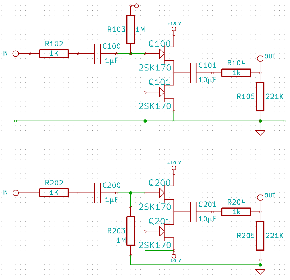
The standard B1 has ~1050r output impedance, way above the <=100r suggested for your EQ circuit.
The DCB1 substitutes a 220r for the 1k0 to lower the output impedance to ~270r. Still too high.
Pass suggests that the 1k0 can be reduced but at increased stability issues as the resistance is lowered.
He quotes 100r as a likely minimum but adds that stability should be checked. That 100r gives an output impedance ~150r. This is still outside the EQ recommened source impedance.
The B1 can be used as a buffer after to EQ to send the signal on to another receiver.
I would suggest that a different buffer with much lower output impedance be used to drive the EQ.
Most filters are calculated assuming Rs=0r0 and Rload=infinity.
As these source and load impedances close in from the theoretical, the more the filter must be altered to keep the same filtering characteristic. This is not easy. I cannot recall seeing a paper explaining how this can be done. I certainly can't do it, but then I'm still very early in my learning of electronics.
There is one exception that is easy to correct.
When the first section of the EQ is a passive, single pole, low pass filter, i.e. a series resistor (R) followed by a grounding capacitor (C), then it is easy to calculate the new values of the passive components.
The R before the cap assumes Rs=0r0.
If instead you substitute R = R' + Rs, you can find a value for R' that keeps the low pass filter exactly as intended. C remains unchanged and any EQ after this first low pass, sees exactly what theory requires of it.
What if i would use a balanced zen line stage at the input. This has 221Ohms, and could be lower according to NP, although the 221Ohms seems to be the best. This could also solve my problem of converting single ended inputs to balanced.
Hi.
I have (cross-)read approximately 400 pages about the B1, symmetric voltage supply, capacitor-less design, regulated PSUs and PCBs available via GB.
I think I wanna keep the I/O-caps and build two symmetric regulated PSUs that share he same unregulated* DC-source.
Anybody got a good, clean "two mono" layout for Salas regulated PSU or a B1 with caps? No need for input-selection. Boards could be PCBs via GB or perf board(?).
*Well, maybe a little regulation.. transformer, rectifier, electrolytic C, film-cap, regulator, film-cap, ....
Hello Luda,
the prototype of my preamp/crossover uses a 10K pot at the input without problems. Just make 2 pairs of outputs, one for your Zen and one for your headamp. Why would you put a switch inbetween, you can use them in parallel.
I currently have a 10K Alps Blue pot at the input of my B-1. I want to try the B-1 with the volume pot bypassed, purely as buffer without volume control. Do I just desolder the input and output wire from the pot and solder on a 10K resistor between the wires? What would happen if I didn't use a 10K resistor? TIA
Hi,I want to try the B-1 with the volume pot bypassed, purely as buffer without volume control. Do I just desolder the input and output wire from the pot and solder on a 10K resistor between the wires?
you don't need extra resistors.
remove the pot.
You have two input wires.
Signal goes to +IN, the other goes to Signal Ground.
You can leave the pot in place and just move the Signal wire from the top of the pot to the wiper.
This reduces the input impedance to the same as the pot value. But, you must keep the pot at maximum position. This will do as an experiment until you decide what solution you need permanently.
If you have access to other nice polypropylene caps then go for those. The Axon are just average and you can find better for not to much money.
Gen 1 Sonicaps sound great in B1.
also change the 4 1K resistors to 330r
using PRP or Naked Vishays it makes a huge difference.
Gen 1 Sonicaps sound great in B1.
also change the 4 1K resistors to 330r
using PRP or Naked Vishays it makes a huge difference.
While they are quite spendy, I'm glad I tried the naked Vishays.
An externally hosted image should be here but it was not working when we last tested it.
Hi,
you don't need extra resistors.
remove the pot.
You have two input wires.
Signal goes to +IN, the other goes to Signal Ground.
If I do this without resistors, what kind of input impedance is it presenting to my DAC's output stage?
I would not try that.
Nelson says 220r is about as low as you can go
without getting some oscillation type distortion.
Nelson says 220r is about as low as you can go
without getting some oscillation type distortion.
While they are quite spendy, I'm glad I tried the naked Vishays.
An externally hosted image should be here but it was not working when we last tested it.
If I do this without resistors, what kind of input impedance is it presenting to my DAC's output stage?
Nelson Pass's B1
Hello guys! I would like to build a Nelson Pass's B1 buffer. I have try to order one with the matched transistor but I can not get the order from Passdiy.
Do you have or know how I can just order one of this boards and matched transistors.
and also will I need to keep the input caps in my amp after I use this B1?
Thanks guys!
My 4 Naked Vishay 330r's are staring at me on my desk waiting for the final parts, some caps, to come in.
I will be mixing 2x 1uf Obbligato Premiums & 2x 10uf PETP Russian K73-16's:
Obbligato Premium 1.0uF (630V) matched pair on eBay.ca (item 230403210769 end time 19-Oct-10 05:33:24 EDT)
10uF 63V PETP Capacitors K73-16 . Lot of 10 on eBay.ca (item 160471063880 end time 01-Oct-10 06:32:14 EDT)
I also have some 1uf K73-16's hanging around & we'll see if I use them.
Will post pick of the finished board as soon as I get the remaining parts installed.
While they are quite spendy, I'm glad I tried the naked Vishays.
If I do this without resistors, what kind of input impedance is it presenting to my DAC's output stage?
Bigaudio.I would not try that. Nelson says 220r is about as low as you can go
Post 2645 says the pot is on the input to B1. He was not asking about the output resistors of the B1.
The standard B1 has a 1M at the input followed by the 25k pot feeding the Megohms input impedance of the jFET.
Removing or shorting out the pot will increase the input impedance of the standard B1 from 25k to 1M0.
I have no idea what the output of your DAC is or requires.
Does your DAC have a current output or a voltage output?
Does your DAC have a users manual?
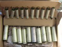
Got these in the mail today, 20 (10x10) K73-16 Russian Caps of both 10uf & 1uf rating. I will be pairing these up with some Obbligato Premiums that I have on the way in my B1 build. From everything I've been reading these may be a good mix n match with the Obbligatos. As usual, the proof will be in the pudding.
P.S. If anyone is in the Montreal area, it looks like I may have a few extra K73-16caps that I can part with as I now have more than I will need
P.S. If anyone is in the Montreal area, it looks like I may have a few extra K73-16caps that I can part with as I now have more than I will need
Attachments
About to build my first Pass B1 with Russian 1uf K40Y-9 PIO caps and 10uf 100V polypropelene output cap. Also 2 X Nichicon 10,000uf 35V electros. Construction on Vero brd. and into a black Hammond Al case. Silver solder and pure silver hook-up wire.
I have a Toshiba laptop 19V 3.5A SMPS I will be using to power the unit. I have read where others have used SMPS with no ill-affects.
I recently built the ESP P37A descrete component preamp for a Malaysain friend and liked the natural sound so thought I may Pass (not) on Pass.
Solid State Audio Projects - Elliott Sound Discrete transistor preamp P37A - DIY Audio Projects Photo Gallery
About to build my first Pass B1 with Russian 1uf K40Y-9 PIO caps and 10uf 100V polypropelene output cap. Also 2 X Nichicon 10,000uf 35V electros. Construction on Vero brd. and into a black Hammond Al case. Silver solder and pure silver hook-up wire.
I have a Toshiba laptop 19V 3.5A SMPS I will be using to power the unit. I have read where others have used SMPS with no ill-affects.
I recently built the ESP P37A descrete component preamp for a Malaysain friend and liked the natural sound so thought I may Pass (not) on Pass.
Solid State Audio Projects - Elliott Sound Discrete transistor preamp P37A - DIY Audio Projects Photo Gallery
I am very interested in using an SMPS to power my B1. What exactly have you heard about this approach?
SMPS forB1
I'm currently using an old Dell notebook adapter (20V 3.5A) with good results - sounds better than a simple LM317 series regulator circuit I used for comparison.
I am very interested in using an SMPS to power my B1. What exactly have you heard about this approach?
I'm currently using an old Dell notebook adapter (20V 3.5A) with good results - sounds better than a simple LM317 series regulator circuit I used for comparison.
- Home
- Amplifiers
- Pass Labs
- B1 Buffer Preamp