I don't think that there are any active group buys, but someone may be willing to part with a set of boards.
The rest depends on how you build it. Builds typically set the gain at around 20 dB.
Power is set by rail voltage and bias. The AJX can scale fairly easily from around 30 to 100W, a straight (mosfet input) AX can go higher if you can live with the heat. So can an AJ-X if the inuts are cascoded.
The rest depends on how you build it. Builds typically set the gain at around 20 dB.
Power is set by rail voltage and bias. The AJX can scale fairly easily from around 30 to 100W, a straight (mosfet input) AX can go higher if you can live with the heat. So can an AJ-X if the inuts are cascoded.
The boards are still avaialble as described here:
AJ-X: http://www.diyaudio.com/forums/group-buys/163900-aleph-j-x-pcb-group-buy-2nd-run.html
PS boards: http://www.diyaudio.com/forums/audio-sector/149672-universal-power-supply-pcb.html
AJ-X: http://www.diyaudio.com/forums/group-buys/163900-aleph-j-x-pcb-group-buy-2nd-run.html
PS boards: http://www.diyaudio.com/forums/audio-sector/149672-universal-power-supply-pcb.html
is this true, 10watt 33k for RG
I am just looking at RG, RP, P1, RS. Can You tell me what you are useing for these components.
I am thinking of changing the Power Transistors to 190W 30A IRFP240 subsitutes, what do you think ? I am ready to order now but dont have enough money for everything if I buy $14. MOSFET(s). I have attached the data sheets below for the two MOSFETs I have considered.
http://www.vishay.com/docs/91210/91210.pdf
http://www.nteinc.com/specs/2300to2399/pdf/nte2376.pdf
Bill I used this to calculate wattage.
I am just looking at RG, RP, P1, RS. Can You tell me what you are useing for these components.
I am thinking of changing the Power Transistors to 190W 30A IRFP240 subsitutes, what do you think ? I am ready to order now but dont have enough money for everything if I buy $14. MOSFET(s). I have attached the data sheets below for the two MOSFETs I have considered.
http://www.vishay.com/docs/91210/91210.pdf
http://www.nteinc.com/specs/2300to2399/pdf/nte2376.pdf
Attachments
advantrage to using high current MOSFETs ?
High Bill,
I am stil looking for what parts to order for P1 & RP if I use JFET, is RP 1.5Kohms ?
I have to choose Power MOSFETs now and have noticed a replacement for IRFP240, the NTE2376 MOSFET, N–Ch, Enhancement Mode High Speed Switch by NTE Electronics Inc., it is 30amp & 190watts, here is the data sheet
http://www.nteinc.com/specs/2300to2399/pdf/nte2376.pdf , can I subsitute this power MOSFET for the IRFP240 20amp 150watt, I beleive it will last longer all other things being equal, and life span of the amplifier is a major concern of mine ?
Thank You for your help, I know I must ask allot of stupid questions, but I am trying as best I can, I probibly have allot of brain damage from all of the drugs I used to take for 20 years, because my memory is very poor these days, if I ask you the same question twice I am still doing the best I can.
Nope, Bill already told you that - you posted an AJ BOM and you are building an AJ-X, right? With a schematic you can update the BOM to include the missing parts.
Remember the -X is symmetrical. You wouldn't be too far off doubling that BOM per channel (assuming it is right, which I can't verify without a schematic) That would give you a few extra parts, but you'd have everything.
Be sure to order extra output devices for matching - at least 50% extra. So if using 12 output devices per channel, get at least 36 devices. Better yet get 50 since they come in tubes of 25 and you have a better chance of getting devices from the same lot in a full tube.
High Bill,
I am stil looking for what parts to order for P1 & RP if I use JFET, is RP 1.5Kohms ?
I have to choose Power MOSFETs now and have noticed a replacement for IRFP240, the NTE2376 MOSFET, N–Ch, Enhancement Mode High Speed Switch by NTE Electronics Inc., it is 30amp & 190watts, here is the data sheet
http://www.nteinc.com/specs/2300to2399/pdf/nte2376.pdf , can I subsitute this power MOSFET for the IRFP240 20amp 150watt, I beleive it will last longer all other things being equal, and life span of the amplifier is a major concern of mine ?
Thank You for your help, I know I must ask allot of stupid questions, but I am trying as best I can, I probibly have allot of brain damage from all of the drugs I used to take for 20 years, because my memory is very poor these days, if I ask you the same question twice I am still doing the best I can.
Attachments
J74 as constant current source
I am setting up my current source the same as you,with J74, can you tell me what you used for P1, RP, RG, RS, this is all I need so I can order my parts and begin to build this amp.
Thank You for listening.
looking for help
My jx channel is built now. Buuuuut..... When I power up I have 24v dc on the output and the RG resistors of 100r from both outputs to ground get very hot and start to smoke if i leave the amp on...
I have a 2x18v toroid with a crc psu 35,000uf - 4 x 0.47r - 35,000uf . This I split to power both sides of the boards. My Jx uses a 2sj109 with a 2sj74bl as current source p1 as 100r and rp jumpered (RS is 10k). I have no components on the other current source option.
Can anyone advise me of where to look for the source of the issue ?
regards
dave
I cant figure out what is going on.
I am setting up my current source the same as you,with J74, can you tell me what you used for P1, RP, RG, RS, this is all I need so I can order my parts and begin to build this amp.
Thank You for listening.
Scaiff001,
If in the end you decide on the standard IRFP240/9240 most recommendations here on the forum suggest you use the Fairchild parts instead of the International Rectifier items. Seems they have a better transistor.
Just a note. Also, Future electronics has the best price I have found on the mosfets. They are MUCH cheaper. Name brand and all.
Tad
There's more to substitution suitability evaluation and reliability calculations than just looking at the device's maximum ratings. Generally, you'll find folks stay away from NTE devices because they are very expensive. The NTE device you linked to has an input capacitance that is double an IRFP240. It may be a dual die device. You could theoretically use half as many, but heat sinking becomes an issue.
Hundreds, if not thousands, of Aleph type amps have been built with the IR (now Vishay) IRFP240 types. You can expect long life IF YOU PROVIDE ADEQUATE HEAT SINKS.
Fairchild has stopped producing IRFP240 and their replacements, FQA19N20C. The closest Fairchild substitute I found at Mouser, FQA32N20C, has 50% higher gate capacitance, which would probably mean the top end would be affected. They are cheap, though...
Last edited:
Nte2356 mosfet
High Bob,
Because of the price I will go with only eight per channel insted of twelve, do you see no problem with this susitute asside from the price, I might have to waight annother month to complete it, I might also have some more wiggle room with my bias as well, will I ? I am out of my current skill set with this decision.
Thank You for your Help.
There's more to substitution suitability evaluation and reliability calculations than just looking at the device's maximum ratings. Generally, you'll find folks stay away from NTE devices because they are very expensive. The NTE device you linked to has an input capacitance that is double an IRFP240. It may be a dual die device. You could theoretically use half as many, but heat sinking becomes an issue.
Hundreds, if not thousands, of Aleph type amps have been built with the IR (now Vishay) IRFP240 types. You can expect long life IF YOU PROVIDE ADEQUATE HEAT SINKS.
Fairchild has stopped producing IRFP240 and their replacements, FQA19N20C. The closest Fairchild substitute I found at Mouser, FQA32N20C, has 50% higher gate capacitance, which would probably mean the top end would be affected. They are cheap, though...
High Bob,
Because of the price I will go with only eight per channel insted of twelve, do you see no problem with this susitute asside from the price, I might have to waight annother month to complete it, I might also have some more wiggle room with my bias as well, will I ? I am out of my current skill set with this decision.
Thank You for your Help.
Last edited:
With only 8 output devices, will you increase the bias per device or accept lower output power? If you up the bias, Are your heat sinks up to the task? You need bigger sinks with fewer devices dissipating the same power. Do you know what you'll need to change to accomplish this?
The NTE is really a waste of money. Without doing any reliability calculations, I'd guess it's the difference between 80 and 100 years.
You've agonized over the sound of each capacitor and resistor, and now you're ready to possibly have a rolled off top end? Even 8 NTEs have 1/3 higher gate capacitance than 12 IRFP240s. Nobody has used it, so we don't know how linear it will be in this circuit.
When you can get the Nelson Pass approved IRFP240 for $1.83 each @25 pieces http://www.alliedelec.com/search/searchresults.aspx?N=0&Ntk=Primary&Ntt=irfp240, why would you want to spend so much on NTEs?
Last edited:
Fqa19n20c
You can still find some FQA19N20C here:
FAIRCHILD FQA19N20C is in stock! | Buy FQA19N20C | FQA19N20C | Onlinecomponents.com
I personally would choose these over the NTE part.
Cheers,
Dennis
You can still find some FQA19N20C here:
FAIRCHILD FQA19N20C is in stock! | Buy FQA19N20C | FQA19N20C | Onlinecomponents.com
I personally would choose these over the NTE part.
Cheers,
Dennis
sodering tempiture and time
Durring my research into capacitors and resistors the ones I am committed to have very specific sodering tempiture and time the heat is applied. I beleive I require a sodering station, is this true or am I becomming parinoid of distroying the components with unbridaled heat. Do You have any suggestions or is the sodering station I have found ok, but it is expensive to which will put my project behind another month at $171.63 . Is their something else I can buy having tempiture control that is cheeper, or is the one I have looked over good because I can use it for the rest of my life ? Here is a link to it
SPC TECHNOLOGY|4004|Soldering Station | Newark Canada
Thank You for your time helping us out.
There's more to substitution suitability evaluation and reliability calculations than just looking at the device's maximum ratings. Generally, you'll find folks stay away from NTE devices because they are very expensive. The NTE device you linked to has an input capacitance that is double an IRFP240. It may be a dual die device. You could theoretically use half as many, but heat sinking becomes an issue.
Hundreds, if not thousands, of Aleph type amps have been built with the IR (now Vishay) IRFP240 types. You can expect long life IF YOU PROVIDE ADEQUATE HEAT SINKS.
Fairchild has stopped producing IRFP240 and their replacements, FQA19N20C. The closest Fairchild substitute I found at Mouser, FQA32N20C, has 50% higher gate capacitance, which would probably mean the top end would be affected. They are cheap, though...
Durring my research into capacitors and resistors the ones I am committed to have very specific sodering tempiture and time the heat is applied. I beleive I require a sodering station, is this true or am I becomming parinoid of distroying the components with unbridaled heat. Do You have any suggestions or is the sodering station I have found ok, but it is expensive to which will put my project behind another month at $171.63 . Is their something else I can buy having tempiture control that is cheeper, or is the one I have looked over good because I can use it for the rest of my life ? Here is a link to it
SPC TECHNOLOGY|4004|Soldering Station | Newark Canada
Thank You for your time helping us out.
Attachments
That should be fine. I use this Circuit Specialists Inc. - CSI Deluxe Station w/Analog Display (CSI-STATION1A) changing tips depending on what I am soldering.
Oddly enough, having enough power and a high enough tip temperature is important to avoid overheating the components you are soldering.
Oddly enough, having enough power and a high enough tip temperature is important to avoid overheating the components you are soldering.
Scaiff001,
You would have to look quite hard to find a better soldering station than this one. Many diyers here have suggested this to me. I bought one and am extremely happy with it. It has a bunch of different tip assortments to choose from and you can replace the heat element when needed.
You could also buy some Quad Eutectic solder from Cardas. Fabulous silver bearing solder. Check out there website.
Hakko 936 ESD Safe Soldering Station | 936-12 (93612) | Hakko
Tad
Weller tend to be the most popular followed by Hakko where I am from.
Check out these
COOPER TOOLS / WELLER|WES51|Analog Soldering Station | Newark Canada
COOPER TOOLS / WELLER|WESD51|Digital Soldering Station | Newark Canada
Regarding temperature and time. I find that a hotter temperature is better because the solder melts much more quickly, so you are in and out of there much faster than at a colder temperature.
When I say hotter I don't necessarily mean 100 degrees hotter, it might be 10 to 20 degrees hotter.
Practice on a bit of proto board with some offcut lead wire and you will see what I mean. In the end it will probably come down to personal preference.
It will also depend on the solder composition you are using
Last edited:
A passive line-level crossover (PLLXO) is a good solution
A passive line-level crossover (PLLXO) is a very good solution for a xover that uses no op-amps which destroy sound quality. I need to create a highpass xover for my Aleph J-X at 100Hz just so I am not waisting amp power on low frequency for my satalites, I can use 6 or 12 db for the PLLXO, the formulas I will use are at the following link:
http://www.t-linespeakers.org/tech/filters/passiveHLxo.htm
So, can someone tell me what the input impedance is for the Aleph J-X for my PLLXO calculations
Thank You for all of the suggestions with respect to the sodering station, I have looked at them all and have not made a choice yet because I am not shure, do I need the desodering vacume ? Is it best if I just get it now for all of the changes I will be making with my stero now, I will have to take out and change parts I am not happy with or just to see how different parts sound ?
Input impedance is whatever resistance you're using input to ground.
A solder sucker and wick are useful for rework. However, if you plan to do more than a couple of parts swaps, consider installing sockets until you settle on your final parts. Multiple reheating risks lifting the traces off of the board. Something like this 310-43-164-41-001000 Mill-Max IC & Component Sockets - just snap off a socket. Check lead diameters of the parts you want to swap. There are individual sockets that will accept larger leads a few pages earlier in the Mouser catalog.
A solder sucker and wick are useful for rework. However, if you plan to do more than a couple of parts swaps, consider installing sockets until you settle on your final parts. Multiple reheating risks lifting the traces off of the board. Something like this 310-43-164-41-001000 Mill-Max IC & Component Sockets - just snap off a socket. Check lead diameters of the parts you want to swap. There are individual sockets that will accept larger leads a few pages earlier in the Mouser catalog.
input impedance
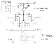
So the input impedance on the given schematic would be R2=221kohms before additional parts for the passive xover ? Is that correct ? I thought it would be R1=22.1kohms ?
Input impedance is whatever resistance you're using input to ground.
A solder sucker and wick are useful for rework. However, if you plan to do more than a couple of parts swaps, consider installing sockets until you settle on your final parts. Multiple reheating risks lifting the traces off of the board. Something like this 310-43-164-41-001000 Mill-Max IC & Component Sockets - just snap off a socket. Check lead diameters of the parts you want to swap. There are individual sockets that will accept larger leads a few pages earlier in the Mouser catalog.
So the input impedance on the given schematic would be R2=221kohms before additional parts for the passive xover ? Is that correct ? I thought it would be R1=22.1kohms ?
Attachments
Last edited:
nope
R1 is input impedance - for unbalanced
2x R1 is input impedance for balanced
R2 is there to reference gates to gnd , and usually one range higher in value than R1 ;
so - their influence on input impedance is max 10%
example - both R1s are 10K
both R2s in range of 100K
both R4s in range of 47K
gain is ~ 4,7 in balanced mode
input impedance for unbalanced 10K // 100K
input impedance for balanced 2x(10K // 100K)
everything is clearer when you know that gates are virtual ground(s)
in any case - this rough calculation is pretty close to what you can measure or sim
If you're planning to use a balanced output preamp to drive this, you'll need a PLLXO on both branches of the signal. Play with it in a circuit simulator to see what happens if you only filter one side.
ZM, I agree with your balanced case, but I think it's R2 (+R1) for single ended. For the low frequency intended for the PLLXO in this case I don't think the 10% matters. If this was a mid-tweeter XO, I'd be concerned. Papa's A75 design uses R1=475R and R2-75K. Input impedance quoted in the article is 75K. I thought opamp - inputs were the virtual ground and the positive needs a DC reference. Mixing signals into the positive input generates crosstalk, but the go into the negative and there is no crosstalk. Could be wrong, though.
Edit:
Following the calculations outlined in the A75 article, the positive input impedance is 243K, and the negative input about 11.5K.
from http://www.passdiy.com/pdf/a75p1.pdf
Figure 10 shows the equivalent network when operating in balanced
mode. On a differential amplifier with such a network, there are four
ways of looking at the input impedance: the common mode input
impedance, the positive input impedance, the negative-input
impedance, and the differential-input impedance. The common-mode
input impedance, seen by signals and noise which are identical at the
two inputs, will be R4 in series with the parallel combination of R5, R28,
and R30 (475 + 1.34k= 1.815k).This input impedance is seen
individually at both inputs for common-mode signal and noise.
At the positive input, this is also the impedance seen by the signal, since
the positive-input network is not attached to the amplifier output, and the
impedance is passive. At the negative input, however, both the
network's passive impedance and what is happening at the output form
the input impedance.
Assuming that the differential signal input is equal in amplitude but
opposite in phase at the two inputs, we see that the operation of the
feedback loop will work to create equal voltages at the gates of the
differential pair transistors. In the example of a positive 1V at the positive
input, the gate voltage will become 0.738V. This same 0.738V will also
appear on the other side of the minus input of 475ohm resistor R2; if it
is being driven at - 1V simultaneously, we see that the current through
R2 behaves as if R2 were 475/1.738, or 273ohm.
Last edited:
- Home
- Amplifiers
- Pass Labs
- Aleph J-X Amp Project