I am lowering the supply voltage to 80V symetrical supply
Because this is the real voltage i am having while using low impedance loads.... this way, i cannot guarantee the amplifier will survive if the user manage to have steady 100 volts each rail (SMPS).
It is possible, because reasons pointed in that thread by several forum members, the amplifier will not survive to very low impedance loads when the supply had not voltage drop.
In the name of more safety to Dx amplifier builders, keeping the traditional reliability, i am going backwards, suggesting from now on, to you to use 80 volts supplies.
A matter of fact, as i told you folks, it was tested, but not unders steady 100 volts as i have not that huge supply....so...untested under this voltage and i cannot guarantee it gonna survive to heavy duty under this voltage.
So, Eesbiboi and other folks interested, i am removing the guarantee i gave the amplifier will be reliable using 100 volts supplies and i am dropping down to 80 volts, as this is the voltage i have tested and proved i can trust.
SOA means safe....does not means the transistor will be destroyed if instead of 1 amperes under 100 volts you make it drain 1.1 ampere....in the reality it can hold much more than these graphics shows.... these graphics shows the guaranteed maximum operation current related the voltage... but there are more room because the transistor manufacturer safety room.... means the transistor can hold more, but the specify this way to me more safe the them.
Also 64 volts condensers can hold much more current.
I am going backwards not because i do not believe the amplifeir will survive.... the real problem is that i fear the use folks can give to it, some may install lots of speakers in parallel, some passive crossovers...long lines of wiring to speakers and these speakers can have a lower impedance compared to the indicated impedance... and this can kill almost all amplifiers.
Going to the safest side of the crowd..... now guaranteed till 80 plus 80 volts only and safe lowest impedance to 4 ohms...... so...it is not a kilowatt amplifier anymore.
Maximum output power, to 4 ohms will be around 650 watts... this means the amplifier is now 1.3 Kilowatt amplifier when stereo was assembled... and a half of that at 8 ohms..undistorted, unclipped using continuous 1 Khz signal at the input... tested with 4 ohms resistive load and 1uf in parallel.
regards,
Carlos
Last edited:
[snip]SOA means safe....does not means the transistor will be destroyed if instead of 1 amperes under 100 volts you make it drain 1.1 ampere....in the reality it can hold much more than these graphics shows.... these graphics shows the guaranteed maximum operation current related the voltage... but there are more room because the transistor manufacturer safety room.... means the transistor can hold more, but the specify this way to me more safe the them.[snip]Carlos
Carlos, your doing it again, being very irresponsibly. The SOA curve means just what it means, that there is NO GUARANTEE that the transistor survives beyond the curves. So DO NOT design outside of the curves!
If you do not know how to do that (and there's many who don't, it's not a shame), ask someone who does. That is also a function of this forum.
jd
Carlos,
While we are on the subject of huge power amplifiers would it be to soon to mention the possibility of designing an amp to direct drive low impedance ribbon speakers without a transformer. The voltage requirements of this type of design would of course be very low, say 15-18 volts, also requiring many multiples of output devices. The current demands would be in line with the Tryon of course.
There has been discussion of this before on this forum, but nothing ever came of it. I believe we are in the 0.3 to 0.5 ohm range here.
Tad
Carlos,
I do (edit) NOT want to give the impression that I am against you or against high-power amps. I am not. Maybe to clarify the issue with SOA. Contrary to what some people belief it is NOT about power dissipation, it is not about V * I, it is about the combination of V and I.
As you saw in the SOA graph I posted before, as an example, at 100V across the transistor (Vce) it can only carry 500mA. That is only 50W for a 200W transistor, but as said, it's NOT the power. The problem is secondary breakdown: at that high Vce, the current trough the transistor tends to concentrate at a spot on the chip that is a bit hotter than other spots. Because of the concentration, that spot gets even hotter, and you see what happens: runaway, local overheating and destruction. Poof! Gone.
Back to the amp. If I have 80V supply, then I only have 80V across the transistor when Vout = 0, right? With Vout =0, Iout (which is Ic) also = 0. So what's the problem? The problem is real-world speakers. Real-world speakers have phase shift between I and V, depending on the frequency, and depending on the xover filter. That phase shift is the cause that at the Vout=0, the Iout is NOT =0, so the transistor is still required to give output current. It's even worse: you get the situation that for instance with negative Vout, it still is the UPPER transistor that has to deliver the output current! So in that case, Vce across the transistor is even larger than the supply voltage and the current can still be relatively large. This is when the SOA comes in and when the poof! comes in.
How do we avoid that? First you decide on what you want this amp to drive. For a nominal 8 ohms speaker, you should be prepared for a minimum of say 4 ohms. You can draw that 4 ohms into the SOA curve: if you have 80V supply the line goes from point 0V/20A (80V/4ohms) to the point 80V/0A.
If this line does NOT cut the SOA line, you're OK. If it does, you can double the output devices which is the same as saying the min load is now 8 ohms, this 8 ohms line goes from 0V/10A (80V/8ohms) and 80V/0A. This line is lower in the graph and if the SOA line is not cut, you'r OK. If it still cuts the SOA, add another pair output devices and adjust the apparent Rload. Etc.
BUT we've not included the 45 degree phase shift! What that does is make the Rload line (which is called, unsurprisingly, the load line) not straight but with a bulge in the middle, an ellipse! And that ellipse of course cuts the SOA line quicker than the straight line. That means you need to add more devices than you thought looking only at the load resistance.
So far so good?
jd
Last edited:
Building HIGH power audio amplifiers is a way of doing things for some people. I am guilty as charged. I think that some folks like to do it and some don't. I like chocolate and some like strawberry and there is vanilla for all the others....
Somewhere in my thoughts last night bought my attention to the serious dangers of building SMPS to power these horsepower (746 watts plus) beast of amplifiers. I want to do both. WHY you ask? Cause I can, and maybe I will.
Some people play with fire. Some people play with water. Some people play with wind. Some play with mud soaked in gasoline lit by the flames blown by the wind.
I have been on fire, bare skin covered with gasoline, over 2 square feet of my body. Do not try this at home.... IT IS Dangerous.... but I am alive to tell the tale. And I have a very small scar to prove my misadventure....
Mean time back to the drawing board to masturbate my brain further....
Janneman,
thanks for that tutorial.
It is already in your web page for those that care to look.
It is also in David Eather's paper.
D.Self deals with it in detail.
What is the point in repeating all that information when no one is listening?
I am listening, THANKS Janneman
Carlos, your doing it again, being very irresponsibly. The SOA curve means just what it means, that there is NO GUARANTEE that the transistor survives beyond the curves. So DO NOT design outside of the curves!
jd
Tell that to the dozens or so of PA amp manufacturers out there. +/-65/130V class H with *four pair of C5200/A1943* that are rated to run 2 ohms and actually do???? When the 2nd rail kicks in, 65 squared divided by two is a whole lot more than 600W!!!! Personally, I would use 8-10 pair, but the math says 14+. This kind of "skimping" isn't the exception - it's the rule. And they sell this stuff. If you build with about a factor of 2X what the bean counters do commercially you're probably pretty safe, actually.
Hi,
what's the bias in the various stages of a ClassH amplifier?
What is the temperature of the various stages of a ClassH amplifier.
What is the duty cycle of the various stages of a ClassH amplifier.
Can these answers be used to correlate de-rated SOAR to output device stress?
what's the bias in the various stages of a ClassH amplifier?
What is the temperature of the various stages of a ClassH amplifier.
What is the duty cycle of the various stages of a ClassH amplifier.
Can these answers be used to correlate de-rated SOAR to output device stress?
wg_ski you are missing the point
frugments of information from amplifier A or B cannot complete a picture or comments for an amplifier ...
for class Ab amplifiers the number of outs is reduced while the rest of the product is equiped with input limiter /compresor, sophisticated or not Vi limiters , other similar protection methods that guard various sections of the amplifier like the lltp or the VAS and so on ...
Often designers add to the above mess a marginal trafo that will provide not enough curent to make damages at full clip conditions that will also reduce kg/watt and cost
often the concept of these power amplifiers is to remain working at full clip with a lot of distortion but still remain working and belive me they manage ....best example is crest qsc and behringer amplifiers ....
so the best way to see TRoyan ...has to be as a design ( and as is )
then to see if protection methods are enough
and then to be builted and tested as a complete product to be able to evaluate the all thing with the specific cooling and trafo ....
my personal comment will be something like that ....
high power amplification is a complicated thing but most of all is a question of target what you want to produce ?
power or safety ?
safety or quality ?
then again devide all these targets versus cost
and then built your target and then start the amplifier design and construction ...
finally and once more the schematic of a power amlifier of this rate of power is only the 20% of the story ....protection methods that missing from this design is the the real thing .....personally i could never put an amplifier like that to work in my rentals fleet .... sound wise might be perfect and quality might be exceptional but protection methods are not enough at least to my standards .....
so may carlos had done an excelent job with the basic schematic of the amplifier but then someone else need to advance the protection methods .... even the vi limmiter is way too generic and for this rate of power for sure something more is needed , then again in the input stage is like any other amplifier and that means that is not suitable for this rate of power ....
my 2cents .... or two bullets in the war
Edit:May Andrew have a diferent opinion about all this but sorry facts are facts both Mercedes and toyota manufacture cars but have diferent concept about their products
Last edited:
but the schematic is full of errors or components that are not suitable for the purpose that has been claimed.then again divide all these targets versus cost
and then built your target and then start the amplifier design and construction ...
finally and once more the schematic of a power amlifier of this rate of power is only the 20% of the story ....
Every piece of equipment must provide value for money.
The client gives the designer and builder a budget and a target (brief & specification)
For that money the client either accepts the proposal or keeps looking.
Everyone buys on that basis. "Do I get value for my money?"
it matters not, whether it's a pair of shoes or a vacuum cleaner or an automobile.
I think that means I agree with you.
Except for the irresponsibility contained in the original proposal and what it might do to the health and finances of untrained readers with aspirations to be good builders.
Last edited:
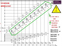
Not to be needed to change the schematic once again
Understand MJL3281 as "modern power transistor"...so, you can replace for other models you find as good or better.... they are in competition, so, they are not so different once compared to the other.
J4215 and J4315
2SC5200 and complementary
MJL4281 seems to be one of the best ones with this case...so... this is the best option...but dear builders can make better choice if they want.
I am testing once again, to have fun, feeling the heat over the load power resistances, the ouput transistors used in my prototype are J4215 and J4315.... matched units, sent my Anonimous last year
regards,
Carlos
Attachments
Last edited:
as what i have observed in the previous discussions,...
some said that the design and some components are not suitable to the power output/psu stated,...that they will not be able to stand 100v of power supply for a long time...
i will still continue to build the design, as what sir carlos said...he built and tested this design and still it works till today...
thats the only thing that pushes me to continue building this design...
for safety,
i will reduce voltage to be use in the design...i will not go further than 80vdc...
since the only trafo i have is a 55 0 55vac...
i guess somehow this will reduce the risk of for the amp and me as the builder...
still i am open for any suggestions regarding the design that will make it much better than what it is now...
this wont be an easy build for me, i cannot assure to make it right away, for finance is one that makes the project go slow...
tnx,
salamat mga kaibigan") ,
,
ees...
some said that the design and some components are not suitable to the power output/psu stated,...that they will not be able to stand 100v of power supply for a long time...
i will still continue to build the design, as what sir carlos said...he built and tested this design and still it works till today...
thats the only thing that pushes me to continue building this design...
for safety,
i will reduce voltage to be use in the design...i will not go further than 80vdc...
since the only trafo i have is a 55 0 55vac...
i guess somehow this will reduce the risk of for the amp and me as the builder...
still i am open for any suggestions regarding the design that will make it much better than what it is now...
this wont be an easy build for me, i cannot assure to make it right away, for finance is one that makes the project go slow...
tnx,
salamat mga kaibigan
,ees...
Last edited:
Thank you, it is working here Eesbiboi.... and the voltage is a little bit higher
than 80 volts...also the transistor quantity i am using is half the quantity suggested and i am pushing it hard.
So, you will not face design problems...because in the real world it is working exactly as the schematic is suggesting.
regards,
Carlos
than 80 volts...also the transistor quantity i am using is half the quantity suggested and i am pushing it hard.
So, you will not face design problems...because in the real world it is working exactly as the schematic is suggesting.
regards,
Carlos
Dear Alexmm, this amplifier will not be assembled soon
Eesbiboi will do it but not now..he will be collecting parts first, ordering transformers and in the future he will build....so....we have no hurry.
Some electronic terrorism happened and this drives people afraid.... we gonna need some time, watching amplifiers built, to people start to assemble....the way always happened.
Soa defenders, datasheeters and other folks made me produce a strategical retreat....just a battle....soon the dust will come down.
I am adjusting and changing things here...just for fun....i love that.....and i have found the bias a little bit dangerous...if the one install a 2K potentiometer than he will be able to overdrive the output stage...and the amplifier may drain all power from the supply while the man goes adjusting or tweaking...this may be dangerous if the one forget the rail protective resistances....so... thinking in these possibilities of human failure, i am asking you dear Alexmm, to try to make a change in the schematic and in the boards.
The VBE multiplier need some tweak to impeach folks to misadjust into dangerous values of current... this way they cannot make hard mistakes..the trimpot in both extremes of resistance will not be harmfull to the amplifiers.
So, there are images that explains and will be attached dear Alex mm...i will be glad to have an email from you to colect your email adress once again, as many format where made these last years and i have lost some of my adresses...also my email adress was changed and the other ones, older ones, had my order to be blocked.
carlos.eugenio1951@yahoo.com
There's a small mistake....i think mine, in the schematic..... we have 10 pairs printed in the schematic and wrong indication of 8 pairs in the rigth lane text...also these transistor options should be printed, as i have tried all them and all them worked and faced full power without problems.
The VBE multiplier has now a fixed resistance and a variable...i hope you find room to change that..i am sorry, i know it is a little bit late to make such kind of modifications.....i am asking your patience with me....my failure discovered when testing again....the former way was good to me..but maybe not good for people less skilled...and we cannot control the ones will be interested to build...i have to make it more safe.
regards,
Carlos
Attachments
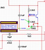
Alexmm made the modifications i have asked
I have perceived the danger in the VBE multiplier fixed resistance adjustment..someone could remove the fixed resistance and substitute by a trimpot and misadjust in a very dangerous way.
This new way.... you will have 200 microamps in one extreme and 15 miliamps to each power transistor in the other extreme of the trimpot resistance.
Suggested resistance adjustment, the preset, should be 150 ohms.
regards,
Carlos
Attachments
- Status
- Not open for further replies.
- Home
- Amplifiers
- Solid State
- Dx Troyan, a 650 watts channel amplifier.