Hi,
If I measure across jfet (after Trimmer) is 0V. between S and G of Q4 is also 0V.
If you logged out - to gnd is an unbearable humming. If I connect in -B1 from the buzz is minimal, only hitting the ear listening to the speaker. I do not understand, the difference is only 20 cm connection cable (unshielded).
The input transformer is 18-0-18. I connected the two poles (18V)of the bridge rectifier and 0V pole is free. The first capacitor is 4600uF Nichicon. C1 and C2 is Panasonic 150 Panasonic UF (not 100uF). 470uF C4 is known unbranded and 0.1 uF capacitor C4 I deleted.
Excuse my English
Greetings and thanks to all
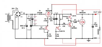
You got to have VGS readings in all Mosfets. See if you have burned Q3 or Jfet under trimmer. 18+18V could give you around 50V rectified. Waisted heat on CCS Mosfet and R1. Only one 18V secondary must be enough for 18Vout although tight. I would use a 22V single secondary Tx and remote sensing. That would certainly give noticeable resolution when using 20cm wires.
If I understand you correctly then you are telling us that the PSU powers your B! successfully. Good.
But you then go on to tell us that the PSU measures wrongly!
Why did you connect it to an amplifier, before finding the error?
I ask because I do not know if there is an error.
I have to know if measures are correct, but still connecting sounds good (except the hum if I connect the ground directly to the negative output of the regulator).
I connected the two poles of 18V to 24V to get out and make comparisons with an output of 18V.
I will connect one pole of 18v and check the components. I'll post the results!
Hi,
I'm having troubles to get the V1.2 working. I build a negative version on perfboard, where 2n5457 is substituted with 2sj103 (turned around of course) and BC556B with BC560C. I get 1.7V out instead of ~15V (24V DC in). R10 is 11k.
I'm referring to Post #2432.
Obviously, the regulator part does not switch on (none of the transistors conducts, the shunt mosfet a bit (those 1.7V). The CCS works. Where ist my twist?
I also made a version with the V1.2 CCS and the juma-style current mirror which works great.
Rüdiger
The original and furhter tested on op-amps low voltage negative is in page 190. That BJT CCS tail one was reported working with IRFP240s by member pidesd a few posts later, was mirrored from positive for him and tested by him. So there must be a way it will debug for you too. Assuming there are zero orientation mistakes, I would consider: 1.The Mosfets to always be IRFP240s. Are they? 2.The buffer BJT (Q8) to be right next to the shunt Mosfet (collector to source, emitter to gate stopper). 3.To use 1k2 resistors R14,15 for 15V scale and 5k6 R6. One mild suspicion would be the 2SJ103's capacitance giving trouble to the error amp's compensation values by changing the loop BW enough. Maybe you got a 2N5459? It wouldn't heat up the BJT with its IDSS in your voltage scale. See about those things, also a pic would help, and we will fix the trouble sooner or later.
The current mirror bit I posted once in a Babo's thread and Juma liked a lot and adopted, is elegant and simple (still not best Zo spec), must be a nice hybrid with the CCS from 1.2. For what application you use it? Had something before and compares any better?
The current mirror bit I posted once in a Babo's thread and Juma liked a lot and adopted, is elegant and simple (still not best Zo spec), must be a nice hybrid with the CCS from 1.2. For what application you use it? Had something before and compares any better?
i dont know if Onvinyl has a +/- regulator, but i m still struggling with mine(amp duty). i ve shortened the input wires a bit and it did help. i ll have to shorten the wire the most i can to see if layout is the problem. right now i ve got about a feet of wiring to my positive not-working-properly reg. meanwhile, i built another +/- 10v reg for my output stage and the same thing happens: the negative reg wont start up until around 5 to 7 minutes. yet the wiring is even more compact, though not optimal, and the layout on my boards is very good. one thing to note is that i use irf9540/540 everywhere on that build wheras i use 240 for my amp on the neg side. also both of my symetric regs are two board configurations.but when powered up and loades individually, they do work fine. i ll report my finding once i get to rewire as it would be in an enclosure.
but when it works my system now sounds very good. for the first time now all my analog regs are sslv1.2. the last reg (+/- 10v) widened the soundtage even more (compared to the sigma22), and smoothened up the presentation, making the experience more emotional. i did not however detected more detail. maybe it s because i dont use remote sensing yet... or maybe it s because i m at the limit of what my digital gear can deliver.
on another note, i completely forgot to take pictures .i know it would probably help.
but when it works my system now sounds very good. for the first time now all my analog regs are sslv1.2. the last reg (+/- 10v) widened the soundtage even more (compared to the sigma22), and smoothened up the presentation, making the experience more emotional. i did not however detected more detail. maybe it s because i dont use remote sensing yet... or maybe it s because i m at the limit of what my digital gear can deliver.
on another note, i completely forgot to take pictures
.i know it would probably help.
Last edited:
Hi,
as you might know, I have build some shunt circuits two or three years ago which were similar to the salas approach. They all shined in the simulator, but had issues with stability in reality. The current mirror thing is rockstable, so I will probably go for it!
Rüdiger
as you might know, I have build some shunt circuits two or three years ago which were similar to the salas approach. They all shined in the simulator, but had issues with stability in reality. The current mirror thing is rockstable, so I will probably go for it!
Rüdiger
Use IRFP9240s/IRFP240s in the shunt position at least, and look in those points of interest I mentioned. No positive build had problems as far as I know from enough reported builds. I use one with 9610/9540 in my current phono, my mate Michael uses 2 positive with 9240s in his phono, RCruz have made 4 with 9610/9240, all in use for long. Also 5V DAC ones in UKR recently shown here. The original negative built in Oz for beta at -15V worked right away as reported. There is the layout in page 190. You did not give me details. What are the Mosfets used? Terminal cap? Load? Changed those resistor values? To have the buffer BJT as intimate to the shunt Mosfet as I mentioned can make a difference. Its distance to the error amp is not critical. You can also delete the compensation from collector to base of error amp, put it across the base of the buffer Q8 to force ground. 120pf+220R when used as such and also skip R7,9 base stoppers. To be sure the problem isn't elsewhwere, just skip the buffer. It must work instantly if its instability with the output CFP.
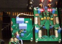
P.S. Quick photo. V1.2 with 9610/9540 feeding 2ch/6 stages at 240mA CCS 47.5Vout 100mA consumption, remote sensed. Buffer BJT stuck underneath shunt MOS far away from error amp. 10uF MKT + 0.5R across its output.
P.S. Quick photo. V1.2 with 9610/9540 feeding 2ch/6 stages at 240mA CCS 47.5Vout 100mA consumption, remote sensed. Buffer BJT stuck underneath shunt MOS far away from error amp. 10uF MKT + 0.5R across its output.
Attachments

is bc556b ok for the bjt cascode? could it be the source of my problem?
If the LED is not lit strongly then some oscillation in the ccs. Not the bjt type. If the cascode bjts aren't tight to the ccs control bjt is the reason. If you can kick start the reg by touching the ccs gate stopper with a probe then that's it. If it gets warm, it may kick start alone at a point, and then works clean. You may also go 82R gate stoppers for 9540 series. They seem more capacitive than in data, since their ygfs is actually stronger than 9240s.
Thanks Salas. Since I use different devices here (2sj103 and BC560) the pinout is different anyway.
You'll have a hard time to guess my mistakes, I think...
Rüdiger
Just follow my schematic looking at the build, forget layouts shown for a while. Is it 100% compliant for connections at least given the pin outs of your semis? BC560 is like 556 for pin out BTW. 2SJ103 is SGD from left to right as we face it, and is P channel. Check carefully. It would need to go as in attached.
Attachments
- Status
- This old topic is closed. If you want to reopen this topic, contact a moderator using the "Report Post" button.
- Home
- Amplifiers
- Power Supplies
- The simplistic Salas low voltage shunt regulator