It has the classical error of misunderstanding maximum output swing.
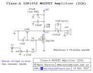
In the positive direction, this would be (Vdd-Vq)Rl/(Rd+Rl)
In the negative direction, this is a bit more complex and depends on how far you want to go into saturation with the MOSFET, but it will be about Vq-2V,
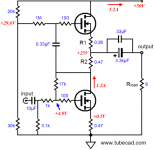
where Vq is the quiscent voltage on the MOSFET drain (adjusted by the pot, this also changes idle current), Vdd is the power supply, i.e. 24V, Rd is the 15 ohm drain resistor and Rl is the load. Assuming an 8 ohm load, you get about 4.17V in the positive direction, and about 9-10V in the negative direction, which results in very asymertical clipping and quite serious reduction in maximum output power before clipping - only about 1W into 8 ohms.
Although it is possible to calculate maximum swing, it involves a compromise regarding distortion, so your best bet would be to measure with a scope, adjusting for symetrical clipping on a triangle waveform, while observing the linearity of the triangle. Themn listen, and fine-tune as needed.
In general, you will have to adjust a larger idle current, and Vq will be less than half Vdd, about 7-8V!
Keep in mind that this adjustment is heavily dependant on the intended load, so this is another thing that must be optimized for.
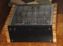
You ight also want to relocate the power resistors to the main heatsink. As it is, the amount of heat generated on them is exactly tehs ame as that on the MOSFET, so it is not logical to give them a smaller heatsink. In the output-swing optimized condition, the restsors develop more heat then the MOSFET, so the more logical it is to put them on the larger sink.
In the positive direction, this would be (Vdd-Vq)Rl/(Rd+Rl)
In the negative direction, this is a bit more complex and depends on how far you want to go into saturation with the MOSFET, but it will be about Vq-2V,
where Vq is the quiscent voltage on the MOSFET drain (adjusted by the pot, this also changes idle current), Vdd is the power supply, i.e. 24V, Rd is the 15 ohm drain resistor and Rl is the load. Assuming an 8 ohm load, you get about 4.17V in the positive direction, and about 9-10V in the negative direction, which results in very asymertical clipping and quite serious reduction in maximum output power before clipping - only about 1W into 8 ohms.
Although it is possible to calculate maximum swing, it involves a compromise regarding distortion, so your best bet would be to measure with a scope, adjusting for symetrical clipping on a triangle waveform, while observing the linearity of the triangle. Themn listen, and fine-tune as needed.
In general, you will have to adjust a larger idle current, and Vq will be less than half Vdd, about 7-8V!
Keep in mind that this adjustment is heavily dependant on the intended load, so this is another thing that must be optimized for.
You ight also want to relocate the power resistors to the main heatsink. As it is, the amount of heat generated on them is exactly tehs ame as that on the MOSFET, so it is not logical to give them a smaller heatsink. In the output-swing optimized condition, the restsors develop more heat then the MOSFET, so the more logical it is to put them on the larger sink.
Last edited:
I ran this amplifier in SPICE.
It is not what we can call HIFI. It is more a great project for fun")
The harmonic distortion was several %. Up to like THD 5%
About the maximum Output Watt.
We have only 0.8 Ampere across 15 Ohm resistor.
The load is 15 Ohm in Parallell with 8 Ohm ... gives like 5.2 Ohm
0.8A x 5.2 = 4.17 Vpeak, as mentioned by ilimzn
Output is 2.95 Vrms which makes 1.08 Watt max output, teoretically
To increase output Watt a little bit
I would make the power resistor 10 Ohm, instead of 15
This gives a current of 1.2 Ampere (12V / 10 Ohm)
It is not what we can call HIFI. It is more a great project for fun
The harmonic distortion was several %. Up to like THD 5%
About the maximum Output Watt.
We have only 0.8 Ampere across 15 Ohm resistor.
The load is 15 Ohm in Parallell with 8 Ohm ... gives like 5.2 Ohm
0.8A x 5.2 = 4.17 Vpeak, as mentioned by ilimzn
Output is 2.95 Vrms which makes 1.08 Watt max output, teoretically
To increase output Watt a little bit
I would make the power resistor 10 Ohm, instead of 15
This gives a current of 1.2 Ampere (12V / 10 Ohm)
You can also optimize the DC at the output and get a bit more, perhaps 2W out, and this will also decrease distortion at low levels because of the increase in idle current, but it will increase the rise of distortion with power because of decreasing Vds of the MOSFET (nonlinear input capacitance... the effect will be less if the source is low impedance).
The original authors comments on this project can be seen at this site.DIY AUDIO PROJECTS - Do-It-Yourself Hi-Fi for Audiophiles My actual test results of this amp will be posted when they are complete. I will say though , it really does boot out big sound for what it is.
There is so much MAGIC in the single ended zero feedback sound that it is easy to ignore its deficiencies . I would like to see and hear of more projects and experiences in this pursuit . I am a big fan of single ended tube amps . Thank you for sharing your hollow state adventure tubem !!!
- Status
- This old topic is closed. If you want to reopen this topic, contact a moderator using the "Report Post" button.
- Home
- Amplifiers
- Solid State
- 2sk1058 mosfet amp