I was PM'd a question relevant to this thread, so I thought I'd bump it to be a bit
easier to find. I was also offered 6P1P for future X-Ray experiments, we shall see...
I've also got JJEL84's working fine in my Fisher X-100-3 (sockets marked 7189).
I have not yet taken the time to peer inside and compare against the originals,
so that tube is also on my short list of sooner rather than laters. Even the Ruskie
6P14's (or was it 15's? I forget) worked without goin' splodie, they just sounded
like they were not biased correctly (not enough quiescent), so I put back the JJs.
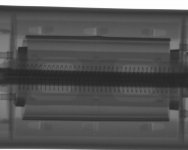
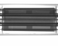
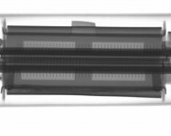
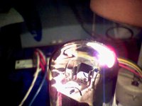
Gimp's 1st 6Π1Π-EB (the one marked with <2> in a diamond)
Yeah, I know the lazy shot off-center, it was a parallax thing.
If I'd shot on-center, you couldn't have made out the filament.
Maybe the tube was leaning slightly or something??? Can't
just stick your hand in there to hold stuff while its turned on...
The last photo (1_1) was unintentional, the tube rolled 45deg...
Also note: This 6P1P was logo'd Winged =(C)=
Other tubes tomorrow... 3 more sets already shot.
Attachments
Last edited:

Thanks Ken.
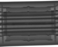
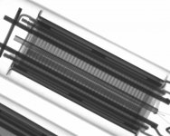
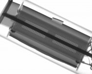
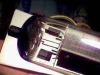
I'm surprised at how close the screen is to the grid. From reading older texts on tube construction and the voltages they operated at I expected to see the screen closer to the plate. I also would have expected the seams in the plate halves to have been alligned with the beam forming deflectors, grid posts and screen posts to shadow them. But the seams of the plate are 90 degrees out from what I expected. I would think the seam would effect the plate opertaion, at least to some degree.
This is really interesting.
I think the seams may help radiate heat away from where the beams strike.
Also sometimes a seam may also have a small inward facing edge. I recall
that was explained to me to have something to do with stopping parasitic
oscillations? Barkhausen or something....
None of the tubes in this set, but look back on some of the older photos.
Also sometimes a seam may also have a small inward facing edge. I recall
that was explained to me to have something to do with stopping parasitic
oscillations? Barkhausen or something....
None of the tubes in this set, but look back on some of the older photos.
Last edited:
I think the seams may help radiate heat away from where the beams strike.
Also sometimes a seam may also have a small inward facing edge. I recall
that was explained to me to have something to do with stopping parasitic
oscillations? Barkhausen or something....
None of the tubes in this set, but look back on some of the older photos.
Exactly!!
Both 6P6 look about the same, so we'll post the redundant set later.
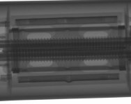
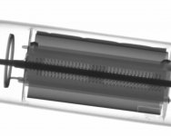
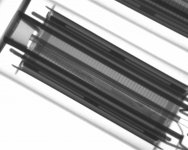
For now, I'll skip ahead to 6AQ5. Gimp's AQ5 pair had some slight internal
differences, or just slight manufacturing variance? You would never guess
any different from the outside view... Or ANY view, except top down...
One AQ5 has grids like a squinty eye. The other (this one) flat, but with
rounded ends where it meets the post... Maybe different tension across
the rods when each was wound?
Interessant, this filament doesn't fill its cathode to the full height of
the grids! And maybe too much sticks out the bottom... Squinty AQ5's
filament doesn't appear to have the same underfill issue. We will see
that in the next update.
Attachments
Last edited:
How does it work?
Fascinating stuff, but how do you get from firing X-rays at your valve to getting an image you can post? Are you using film, then scanning it, or does the machine have a scanned sensor and produce JPEGs directly?
It's great to see the grid alignment for real - the hammer and cutters forensic approach tends to be a bit slow and sometimes inconclusive.
I think there is a scintillator screen, and some sorta fiber optic cone to shrink the
image to a normal sized CCD. Not 100% sure that how mine works, just reading on
the subject in general... Cause I had to photograph the ball grid under a CCD the
other day, and wanted to know if the XRays would damage the light sensor? Yes,
eventually it would damage, but it takes like 3000 or more exposures. I'm not sure
how long that works in real time, ours gives a live image average over 16 frames.
But ours is maybe 30 or 60 frames per second??? Never read actual spec.
Anyways, theres usually some sorta scheme to keep the sensor out of the direct
blast. We are using hard X-Rays like 90KV here... Goes right through gold.
Heliphino?
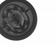
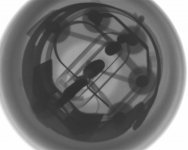
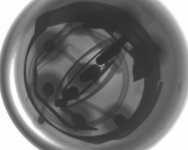
Anyways... the other AQ5, "Squinty":
Does this AQ5 cathode look round to you?
Was the other one round, or bar shaped???
I could't tell if it just looked that way due
to parallax.
Recall the other cathode had an underfill
issue, with a heater that didn't quite reach
the full span of the control gridded area...
No such underfill defect to be seen here,
I'm assuming this example's fill is "right"?
Missing here: Some sorta horseshoe shaped
shorting bar in the base, or maybe that was
some part of the getter? The 6P1P had one
too. Why does this AQ5 appear not to have
one, but the underfilled AQ5 clearly did?
I think all three top down views have shown
evidence of a halo for the getter, so I am
sorta doubting thats what the horseshoe was.
Attachments
Last edited:
Doh! yeah, so thats what it was...
One AQ5 definately got some shoesink up top.
Squinty, shoeless wonder, nekkid as a jaybird...
6P1P got shoe.
--------------------
Looks like I got my topdown pics mixed with the wrong sideviews?
You can clearly see which AQ5 sideviews got shoe and which don't.
Means Squinty was also the one with the underfilled cathode.
Zobsky was tellin me bout some forum guy who said the worst AQ5
ever made sounded better than the best BQ5. We might just have
one of those "worst made AQ5" perfect to test the theory???
Specific names weren't dropped, and I havn't searched to find out
who might have posted such an opinion (yet). But I'm interested
to learn the truth of it.
Last edited:
Copy and paste from Suppo EL84 thread:
I counted 20 G3 turns in my XRay of Ruskie 6P15-EB,
Not counting extra coils in the tightly packed ends....
here the grid ratios compared to el84:
Comparison between 6BQ5 and chinese 6P15, both are true penthodes.
6BQ5 G2 is rates 2W, 300V
6P15 is rated 1.5W, max 200V
the tubes were opened:
spacings between the electrodes were found about to be the same.
Tests were performed with a micrometer, dimensions in mm:
6BQ5 6P15
G2 turns ~27 G2 turns ~ 35
G2 wire dia: 0.06 G2 wire dia: 0.06
G2 turns spacing: ~ 0.98 G2 turns spacing: 0.75
G3 turns: 10 G3 tuns: 21
G3 wire dia.: 0.1 G3 wire dia: 0.1
G3 turns spacing: 2.5 G3 turns spacing: 1.1
Cathode emission coating length in both tubes is ~ 25.5mm
in the 6P15 the suppressor grid has a bigger influence than in the 6BQ5
Steve
maybe not nice to read in this form
I counted 20 G3 turns in my XRay of Ruskie 6P15-EB,
Not counting extra coils in the tightly packed ends....
Last edited:
6P15 etc.
OK, 20 or 21 turns is not a big difference, depends how much you count down to the coiled area of the G3. but surely this G3 is interesting to investigate what means can be used for controlling the 6P15. I am right now on a PP design with it, and i will submittresults, if they are inertesting for the forum. I plan first to give this G3 a slightly positive voltage to sharpen up the knee and then see what THD etc tell me. A negative G3 against GND seems right now not to make too much sense to try for the project right now. But for feedback, just for one stage, does it make sense? Maybe better use the feedback from the 6P15 plate to pre-amp cathode using just a resistor only.
This is then for SE amp only at first step.
bump..
Hey Ken,
Nice meeting you at LSAF... Any chances of your little contraption taking a peek inside a sealed up Tannoy crossover?
This is for a 10' monitor red and to date no schematic exists and i'd like to figure it out.
It is about 3 X 3 X 8" or about the size of an 845. The case is steel and I'm not sure if that makes a difference.
dave
I dunno? Won't take but a minute to try if the machine is already warm.
Obviously I can see right through a GU50's plate no problem. I'm never
timely returning stuff by mail, so entrust someone else in North Dallas
with getting the part back to you if return matters.
Have you tried Dayton WT3 with 8ohm dummy load to see what the Z
curves are doing?
Obviously I can see right through a GU50's plate no problem. I'm never
timely returning stuff by mail, so entrust someone else in North Dallas
with getting the part back to you if return matters.
Have you tried Dayton WT3 with 8ohm dummy load to see what the Z
curves are doing?
Tubesteve: "The amount of humans is increasing, but the amount of available intelligence remains a constant."
I always thought it was not the universe expanding, but us shrinking.
Prolly cause time, space, mass, energy all the same thing on some
low level. More mass = less space, everywhere a constant balance.
Where mass accumulates, space shrinks. So space inbetween looks
like its expanding... Dark energy = StOOpid explaination for obvious.
A black hole is probably not a singularity, but an empty shell of mass
at the even horizon. Why should it fall any further in? It wouldn't lose
any energy in doing so. Gravity at the real center is probably less
than in the shell, and the interior is filled with energy like a Cadbury.
Or maybe energy can't escape the shell on the inside either???
"I'll get you, my shrinkies!" The good doctor knew best...
Last edited:
this particular driver has odd parameters and allegedly an odder crossover. My first step in investigating anything is to try to understand what the original intent was and go from there. A basic parts identification inside the "black box" might give me a clue to this albatross.
dave
dave
- Status
- This old topic is closed. If you want to reopen this topic, contact a moderator using the "Report Post" button.
- Home
- Amplifiers
- Tubes / Valves
- Grid - Screen Alignment (X-Rays)