R14/34 warning
I just realized that the diagrams showing the modded input cap connected to the screw terminals REQUIRE the removal of R14/34 or else you will short the 2.5v. I can take the resistors in or out because I have the caps in the stock location even though they are much larger. Anyone trying any mods to any piece of equipment should be able to follow a schematic. If you are not familiar with following a schematic to verify what you are doing then you should probably just enjoy the amp in it's stock form. Even experienced modders should be prepared to throw away damaged boards when the inevitable occurs and not be disappointed in the product it's self.
I just realized that the diagrams showing the modded input cap connected to the screw terminals REQUIRE the removal of R14/34 or else you will short the 2.5v. I can take the resistors in or out because I have the caps in the stock location even though they are much larger. Anyone trying any mods to any piece of equipment should be able to follow a schematic. If you are not familiar with following a schematic to verify what you are doing then you should probably just enjoy the amp in it's stock form. Even experienced modders should be prepared to throw away damaged boards when the inevitable occurs and not be disappointed in the product it's self.
Lots
I have posted many pictures all along the way. Search my posts in this thread.
I think its kinda strange we never saw a picture of your full modded board scott.
(or im just curious)
I have posted many pictures all along the way. Search my posts in this thread.
Hi all,
Just completed "stage 2" of the build and modded the board. Replacing the inductors went far better than expected - mostly because:
a) I used a relatively cheap, but temperature controlled iron
b) I removed the heatsink before replacing them, giving better soldering access.
c) I took on Sendler's advice about heating one side of the inductor (until the solder liquefies) and prizing it up with a small flat bladed screw driver
d) After prizing it up, completed the extraction by holding the top of the inductor with a pair of long nose pliers, heating the other side until it liquefies and it should easily pull off.
e) Tinned the new inductor solder pads
f) Tinned the board solder pads
g) Soldered while making sure the solder liquefies. May take a couple of goes
h) Measured the resistance between the pads
Interesting that the old 22uF inductors measured between 10-11 Ohms and the new Wurth 4.7uF measures 0.9-1.0 Ohms. Implying about 5x the impedance reduction of due to a reduction in coil length and a further 2x reduction due to increased coil diameter. All good
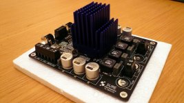
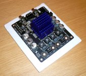
Then I added the nice looking Zalman heatsink (just using an extra tiny 'rice-grain' bit of compound). Getting the legs in the right position was probably the fiddliest bit, but not bad at all.
Then did the full set of input mods suggested by Audio1st.
See the attachments for some pretty pictures.
Stage 3 is to file off the drilled holes in the enclosure (which I did earlier).
Cheers,
Andrew
Just completed "stage 2" of the build and modded the board. Replacing the inductors went far better than expected - mostly because:
a) I used a relatively cheap, but temperature controlled iron
b) I removed the heatsink before replacing them, giving better soldering access.
c) I took on Sendler's advice about heating one side of the inductor (until the solder liquefies) and prizing it up with a small flat bladed screw driver
d) After prizing it up, completed the extraction by holding the top of the inductor with a pair of long nose pliers, heating the other side until it liquefies and it should easily pull off.
e) Tinned the new inductor solder pads
f) Tinned the board solder pads
g) Soldered while making sure the solder liquefies. May take a couple of goes
h) Measured the resistance between the pads
Interesting that the old 22uF inductors measured between 10-11 Ohms and the new Wurth 4.7uF measures 0.9-1.0 Ohms. Implying about 5x the impedance reduction of due to a reduction in coil length and a further 2x reduction due to increased coil diameter. All good
Then I added the nice looking Zalman heatsink (just using an extra tiny 'rice-grain' bit of compound). Getting the legs in the right position was probably the fiddliest bit, but not bad at all.
Then did the full set of input mods suggested by Audio1st.
See the attachments for some pretty pictures.
Stage 3 is to file off the drilled holes in the enclosure (which I did earlier).
Cheers,
Andrew
Attachments
I think on the first board I used a soldering iron tip that was too big, and it was melting 2 traces at once. I've done my 2nd board today with a smaller tip and things went much more smoothly.I think you will find that you need a second cap. One at the dac and one at the stock location on the amp to keep the 2.5v input bias from shorting back through the attenuator or R14/34. With the attenuator loading the dac you may get better sound after removing R14/34. I have been doing my critical listening using digital volume control without the attenuators. This sounded better with the resistors in place to load the dac and cables. I am soldering the coils the same way as you. It is much easier on the new style amps as the heat sink clips right off. Then there is plenty of room.
I am also including a 4.7uF input caps on the sure board, I've soldered them in place of the existing 1.0uF caps and using the same traces on the PCB as the 1.0uF caps, so after looking at the Sure schematic again I can see that R14 and R34 are connected before the input caps so I should be fine leaving them in place with the way I have wired in my input caps by using the holes in the PCB for the 1.0uF caps.
I forgot to include my 2nd input cap on the signal chain in my previous post... Here is how I plan to have things, I'm guessing this should work ok:
AK4396 DAC -> 4.7uF coupling cap -> 4 ft interconnect -> 3.9K shunt stepped attenuator -> 6 inch wire -> R14/R34 (parallel)-> 4.7uF coupling cap (parallel) -> Sure amp module
So, with R14/R34 still in place, this is how things will be.
Even if I remove R14/R34, it would be easy enough for me wire up another 22k resistor in my signal chain as R14/R34 are in parallel according to the Sure's schematic.
I think the reason I was getting mixed up was because in Tripath's TK2050 datasheet they used 20k resistor in series, not parallel.
After reading up on RC filter circuits, I now see that you can have both series and parallel RC circuits that essentially do the same thing in a different way.
Yep these boards are so low cost that if one does fail, then it's cheap enough for a replacement board. I've now ordered a couple of spare boards just in case I do ever fry one. It seems that the only failures so far have been down to overheating...I just realized that the diagrams showing the modded input cap connected to the screw terminals REQUIRE the removal of R14/34 or else you will short the 2.5v. I can take the resistors in or out because I have the caps in the stock location even though they are much larger. Anyone trying any mods to any piece of equipment should be able to follow a schematic. If you are not familiar with following a schematic to verify what you are doing then you should probably just enjoy the amp in it's stock form. Even experienced modders should be prepared to throw away damaged boards when the inevitable occurs and not be disappointed in the product it's self.

Nice info and pics, I've also tried the Zalman heatsink, and I find it can get pretty hot when running at 24v. As I'm using the board in a small enclosure (coffee tin) then I have also used a 60mm computer fan running at 5v, you may need a fan also depending on what enclosure you are planning to use.Hi all,
Just completed "stage 2" of the build and modded the board. Replacing the inductors went far better than expected - mostly because:
a) I used a relatively cheap, but temperature controlled iron
b) I removed the heatsink before replacing them, giving better soldering access.
c) I took on Sendler's advice about heating one side of the inductor (until the solder liquefies) and prizing it up with a small flat bladed screw driver
d) After prizing it up, completed the extraction by holding the top of the inductor with a pair of long nose pliers, heating the other side until it liquefies and it should easily pull off.
e) Tinned the new inductor solder pads
f) Tinned the board solder pads
g) Soldered while making sure the solder liquefies. May take a couple of goes
h) Measured the resistance between the pads
Interesting that the old 22uF inductors measured between 10-11 Ohms and the new Wurth 4.7uF measures 0.9-1.0 Ohms. Implying about 5x the impedance reduction of due to a reduction in coil length and a further 2x reduction due to increased coil diameter. All good
Then I added the nice looking Zalman heatsink (just using an extra tiny 'rice-grain' bit of compound). Getting the legs in the right position was probably the fiddliest bit, but not bad at all.
Then did the full set of input mods suggested by Audio1st.
See the attachments for some pretty pictures.
Stage 3 is to file off the drilled holes in the enclosure (which I did earlier).
Cheers,
Andrew
Last edited:
Is it just Me?...Or is it my Board?..I've been Running mine for a couple of weeks now off a 31.5V HP Supply, and it seems Quite Bright..So much so, that I run it through a Yaqin CD2 with Mullard CV4010's just to to Mellow it out a bit. Now, I've seen these last 157 pages on how to Mod this, but I've got to Wonder Why...Right now I'm running mine Stone Stock on the Low Setting with a Cmoy Preamp into the Yaqin and 4 of my Bozaks and it will Crack the Plaster...I've always thought that I needed a Sub with My ST70 and 1 Pair of the Bozaks...But this can Rattle the Rafters with 4 of them...I just PiggyBack the Bananas, and if I turn it up Too Far and it goes Silent, well, I just turn the Power Supply Off and On, and Bam..We're Rockin' Again..This Board seems to Me to Sound, and Really Put out some Power, Quite Good just the way it Comes....
Last edited:
I just build another module today, including the following mods:
1) replaced inductors with 4.7uH wurth xxl (they get very very hot :S)
2) replaced all output caps with 0.47uF dayton polypro foils
3) added zobel network, 0.47 dayton polypro foils and 15ohm metal film
4) removed diodes
5) removed suppressors
6) removed the fan and placed a zalman heatsink on it (gets almost as hot as the coils :S)
7) input caps replaced with 2uF westcap caps (thx dr_vega) and bypassed with some polypro foils 0.47uF (10 of those on my board right now)
8) replaced the stock buffer caps with panasonic FM's 470uF
9) added 6 more panny fms underneath the board, total capacitance is 5000uF approx
10) removed all unnecessary stuff like the dip switches and r14 r34
Pics coming soon
just one more word for all of you: DO NOT TOUCH THE MUTE TERMINAL OR THE 5V TERMINAL (with your fingers) as the amp starts to put out very high sounds
It fried 2 of my cheap *** test speakers which measure now 1ohm (the board still can power them at low volumes )
Sound is really lovely, no harshness at all which i had with the arjen inductors and wima output caps
Also: dont touch the 5v supply, the other board had a low esr cap on it, and it became slow and sluggish...
1) replaced inductors with 4.7uH wurth xxl (they get very very hot :S)
2) replaced all output caps with 0.47uF dayton polypro foils
3) added zobel network, 0.47 dayton polypro foils and 15ohm metal film
4) removed diodes
5) removed suppressors
6) removed the fan and placed a zalman heatsink on it (gets almost as hot as the coils :S)
7) input caps replaced with 2uF westcap caps (thx dr_vega) and bypassed with some polypro foils 0.47uF (10 of those on my board right now
)8) replaced the stock buffer caps with panasonic FM's 470uF
9) added 6 more panny fms underneath the board, total capacitance is 5000uF approx
10) removed all unnecessary stuff like the dip switches and r14 r34
Pics coming soon
just one more word for all of you: DO NOT TOUCH THE MUTE TERMINAL OR THE 5V TERMINAL (with your fingers) as the amp starts to put out very high sounds
It fried 2 of my cheap *** test speakers which measure now 1ohm
(the board still can power them at low volumes )Sound is really lovely, no harshness at all which i had with the arjen inductors and wima output caps
Also: dont touch the 5v supply, the other board had a low esr cap on it, and it became slow and sluggish...
The diodes are not in the meanwell, but on the board, marked d1 and d2 (next to the power plug)
Why switch to carbon if metal film is recommended in audio?
To do list:
Add potmeter (now powered by an iaudio x5l mp3 player playing flac files using rockbox)(95s/n rate, quite good for an mp3player)
Add soft start module WITH speaker relais (i really hate the pop on sound)
Make a chassis + input select etc.
Maybe add an 7805 to the board (directly soldered on the board) for a fan, as the heatsink gets hot, and it might cool the coils too)
Build another module
Last edited:
Quite rigorous to add a speaker relay and logic just to get rid of the pop sound. Shall I send you some input caps that sound great and don't pop at all?
Then the 7805 and fan... why add more noise, rather than analizing the cause of the heat problem and fix it...
A guy here on a Dutch forum is pondering on sending me his Sure board to make an analysis. He's not a noob on electronics himself either, so it's either that or I will perhaps guide him through it if necessary.
Then there's still that funny config fault on the board to which Sure has reacted rather silly in response to emails about this. It does seem like a salesman answering our questions, so perhaps we get a little more useful answers after they have backed it up by their R&D staff... We'll see....
To anyone using the later boards with larger silver heatsink and MSI fan on, today I powered the fan from a separate L7805CV, but the problem is that the fan doesn't always spin up. Could this because my SMPS is maybe doing some sort of soft start?
I can start the fan spinning if I push it with my finger, but I don't want to have to do this every time...
Also to people worried about the pop sound, maybe using the mute feature would give better results compared to using speaker relays?
I can start the fan spinning if I push it with my finger, but I don't want to have to do this every time...
Also to people worried about the pop sound, maybe using the mute feature would give better results compared to using speaker relays?
Last edited:
5v?
Does the fan have 5v on it's wires even when it is not spinning?
To anyone using the later boards with larger silver heatsink and MSI fan on, today I powered the fan from a separate L7805CV, but the problem is that the fan doesn't always spin up. Could this because my SMPS is maybe doing some sort of soft start?
I can start the fan spinning if I push it with my finger, but I don't want to have to do this every time...
Also to people worried about the pop sound, maybe using the mute feature would give better results compared to using speaker relays?
Does the fan have 5v on it's wires even when it is not spinning?
Quite rigorous to add a speaker relay and logic just to get rid of the pop sound. Shall I send you some input caps that sound great and don't pop at all?
Then the 7805 and fan... why add more noise, rather than analizing the cause of the heat problem and fix it...
A guy here on a Dutch forum is pondering on sending me his Sure board to make an analysis. He's not a noob on electronics himself either, so it's either that or I will perhaps guide him through it if necessary.
Then there's still that funny config fault on the board to which Sure has reacted rather silly in response to emails about this. It does seem like a salesman answering our questions, so perhaps we get a little more useful answers after they have backed it up by their R&D staff... We'll see....
That's me
Very strange, I just don't get it why the board will work with the wrong setting on pin 24. Maybe this is also why the board heats up even while there is no signal on it.
I guess not, because elfishi tried it and it didnt help
One thing I saw in the tripath manual: add 1000pF or so between speaker outputs before the output filter to reduce overshoot (it was in one of the footnotes)
Also: Great input caps do not/barely produce a popping sound. I have 2 westcap 2uF bypassed by the dayton polypro foil 0.47uF, and it barely produces a pop on sound, but sounds great nonetheless
Hi B-force, here too!
Along the road of finding the ultimate mosfets for Truepath I noticed there are fets that get bloody hot and fets that are running cooler. Much cooler I must add, at some point we found fets that run almost entirely cold and sounded better too.
Class D/T running hot at idle is normal because there is always a switching wave and this is already quite high frequent at idle. Class D/T running hot is an overall indication of a bad design or poor components, especially nowadays with the great fets/ power stages around.
From a far earlier point in this thread I have been trying to point this out, but haven't seen any really sane mods in that direction reported, just geek mods like putting big fans on top of it and amazing coolers. Why???!!?
I'm afraid it's rather the TP2050 than the zobel, a 1000pF cap an such... Perhaps it is both, or even some output filter parts, but most likely the output stage itself... Im thinking no wonder that when the TP2050 was still on the shelve at the address of many suppliers there were many suppliers that delivered STA505 instead on a TP2050 order.
I still have a whole bunch of STA505 for anyone who wants to experiment because I decided to only use the STA517B/516B myself from now on....
Last edited:
- Status
- This old topic is closed. If you want to reopen this topic, contact a moderator using the "Report Post" button.
- Home
- Amplifiers
- Class D
- Sure Electronics New Tripath Board tc2000+tp2050