When I look at this I see the waveforms start out at the same time then the green trace begins to lag. If you shift the trace to match levels the lag gets worse. I do not know if this is an artifact of how the waveforms were sampled. I just find it interesting.
When I blow this up I see some spikes have shifted by a few pixels.
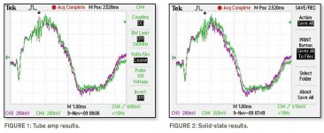
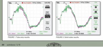
I don't see any lag. I see a change in zero-crossing which points to a difference in level and/or shape.
Look at the peaks on the waveforms that are strong enough in both to compare. They line up exactly.
jd
Attachments
Last edited:
I don't see any lag. I see a change in zero-crossing which points to a difference in level and/or shape.
Look at the peaks on the waveforms that are srong enough in both to compare. They line up exactly.
jd
I downloaded the pdf and the graphs are reversed to yours Jan.
Attachments
You folks sure know how to confuse things. ;-)
Confusion fit's in well with this thread
")
The offline version (downloadable pdf) appears incorrect.
You folks sure know how to confuse things. ;-)
'You folks'? I think I must refer you to the author
jd
When people post images and can't determine what they are looking at, it confuses things.
You mean you don't know what you are looking at?
jd
Jan, please we are trying to do serious comparisons.
Indeed. Jan pointed out, seriously, that the scope readings do NOT show what the author claims they show (e.g., delay). Do you have an alternative explanation of why all of the larger peaks line up perfectly along the time axis for both the tube and the transistor amp?
Here's more Serious Comparison: there's no quantitation over what "fits" best, just a "gee, the tube one looks closer than the transistor one." Now a major part of that is indeed a matter of scope adjustment, but there's certainly going to be some difference. And just eyeballing is not exactly a real judgment- frankly, if I had been handed the two charts without any information about what was being compared, but just asked the question of which output appears to follow the input more accurately, I'd have picked the other one. Whose eyeballing is correct? I don't know, but when the author had the actual data in hand, it would have been nice if he'd done more with it.
So, get serious. If you (or Ed) think these data DO support the author's contentions, please explain why.
Yes, that forms a really good RC filter with a very low cutoff frequency of about 10Hz. In conjunction with high speed rectifiers probably the best (and most simple) solution to get rid of hum and noise from the power supply.
Putting half the capacitance on either side of a series resistor has many benefits, even of the resistor value is quite small, like 0.2 ohms. You get the extra 6 dB/octave ripple reduction, but you also get better ground noise isolation. If you are using a star ground, make the star lie at the junction of the downstream pair of capacitors. Let the junction of the upstream pair of capacitors be a spoke off of the main star ground that forms a star-on star arrangement. The two upstream capacitors and the transformer center tap are connected together there. The high rectifier spike currents are thus resolved at the upstream secondary star and do not pass through the main start ground.
Cheers,
Bob
I downloaded the pdf and the graphs are reversed to yours Jan.
Thanks for clearing this up, Terry. I was confused also when I read this article in AX. The graphs were apparently published backwards, and the solid state design tracks the input signal better. I wonder if that changes the author's conclusion?
Cheers,
Bob
But Bob, what if we were happy with .5 ohms, BUT we added inductance? Would it not be even better?
Hi John,
Yes, definitely. In fact, a little bit of inductance in the 0.2 ohm resistor would not even hurt. But the nice thing about a real inductor with a well-chosen upstream capacitor might be the increase in conduction angle of the rectifiers. I have not tried this, however.
Cheers,
Bob
Hi John,
Yes, definitely. In fact, a little bit of inductance in the 0.2 ohm resistor would not even hurt. But the nice thing about a real inductor with a well-chosen upstream capacitor might be the increase in conduction angle of the rectifiers. I have not tried this, however.
Cheers,
Bob
I was surprised when I looked at conduction angles. A decently sized inductor really does spread it out, but what surprised me was how much just the transformers inductance and resistance spread it.
Attached is just the voltage look across the transformer. You can see the voltage sag when the diode begins to conduct and then the voltage rises as the capacitor charges and the still is energy going into the capacitor till just a bit (about 2.5ms) after 90 degrees. This is just a transformer, diode, capacitor and load resistor.
Of course others may read this picture however they want to.
Attachments
Last edited:
I don't see any lag. I see a change in zero-crossing which points to a difference in level and/or shape.
Look at the peaks on the waveforms that are strong enough in both to compare. They line up exactly.
jd
Jan,
When I cut it, paste it and blow it up to a full page size (English 8.5 x 11) I see about a 3 pixel offset on some of the spikes. Full blown proof! Of course not. Valid data, not really. Does the author have more detailed information, don't know. Enough to try the experiment myself? Yes, since it is trivial, as I have all of the parts.
As to AX mixing up the graphs, that is not uncommon.
The advantage of publishing is that sometimes people who know more than you do, write in and increase your level of knowledge.
The biggest issue to me is that I do not expect to see that much difference between the input and output of any amplifier!
ES
Last edited:
When people post images and can't determine what they are looking at, it confuses things.
John,
No need to get your knickers in a knot!
The error is the magazines and I have notified them.
FWIW, I don't see much substance in the whole article. It needs
to be done more scientifically with much better plot resolution.
One thing I did like was the NP interview.
Terry
Last edited:
Terry, I needed to know what the problem was, BEFORE I could even know whether it was a problem or not. Ed Dell, bless his soul, runs a pretty loose ship when it comes to technical proof-reading. He did essentially the same thing to Walt Jung and me, 25 years ago. Screwed up the captions. Never seems to learn.
In any case, I don't need to be sniped at by others, who hold different views, especially on the Blowtorch tread.
In any case, I don't need to be sniped at by others, who hold different views, especially on the Blowtorch tread.
- Status
- Not open for further replies.
- Home
- Member Areas
- The Lounge
- John Curl's Blowtorch preamplifier part II