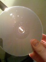
Even the glass is still clear on the 304
Mine (mk2) has become a new acryllic window.
Where did you get the window? or Did you make it yourself?
Andy
.
Thank you for the manual Bassisvus. It is my first Grundig Manual to see and it has better markings than from philips. As you can see in the manual pin 1 is the right for steeling the signal after I/U on the Cd 9000 too. The ground you can connect to pin 3.
... seems like dutch people prefere plastics there in each time
I tried different display. Now I take a scratch-firmer and easily colored genuine glass.
One 4,5 x 13 and another for behind 4,8 x 13,3 cm and 3 mm thik. With only one glass I got problems with fasten. The adhesive was from the front visible. The two glass stuck together can simply stick in from behind like the original.
The first glass must become cleanly polished at the edges. I put 600 - 1000 sandpaper on a mirror, sharpen edge flat and provide it with a phase. A finished display needs approx. 3-4 hours of work.
That replaces then perfectly the blurred nascent first part of the original display. If you have problems with the rear and marked part of the display, or only have one with an ugly türkisen inscription from a MKII, then you can leave this part also completely away. For that I stick instead then a sunning protective plastic film from car accessories on the back of the new first part of the display.
If someone sends me a MKII decoder-board in good working order (TDA1541 is not important, can taken out), I send a new display back.
I wish all people a happy new year!
Show-material made of acryllic 6mm for in a optician shop. (my work) Had to machine only the sides.
... seems like dutch people prefere plastics there in each time
I tried different display. Now I take a scratch-firmer and easily colored genuine glass.
One 4,5 x 13 and another for behind 4,8 x 13,3 cm and 3 mm thik. With only one glass I got problems with fasten. The adhesive was from the front visible. The two glass stuck together can simply stick in from behind like the original.
An externally hosted image should be here but it was not working when we last tested it.
An externally hosted image should be here but it was not working when we last tested it.
The first glass must become cleanly polished at the edges. I put 600 - 1000 sandpaper on a mirror, sharpen edge flat and provide it with a phase. A finished display needs approx. 3-4 hours of work.
An externally hosted image should be here but it was not working when we last tested it.
That replaces then perfectly the blurred nascent first part of the original display. If you have problems with the rear and marked part of the display, or only have one with an ugly türkisen inscription from a MKII, then you can leave this part also completely away. For that I stick instead then a sunning protective plastic film from car accessories on the back of the new first part of the display.
An externally hosted image should be here but it was not working when we last tested it.
If someone sends me a MKII decoder-board in good working order (TDA1541 is not important, can taken out), I send a new display back.
I wish all people a happy new year!
Bernard could have a board
My re-fitting of window did not took such a long time
Machined a small rivet on the two sides (milling on drilling machine) wich fits in the plastic frame of front. Re used the greyisch screen behind the window.
Btw it was a GERMAN acryllic sheet.... (flair frames), had to remove/polisch the decals FLAIR from it.
My re-fitting of window did not took such a long time
Machined a small rivet on the two sides (milling on drilling machine) wich fits in the plastic frame of front. Re used the greyisch screen behind the window.
Btw it was a GERMAN acryllic sheet.... (flair frames)
, had to remove/polisch the decals FLAIR from it.
Last edited:
UHU Glaskleber ... but is condemned expensively 6,49 Euro and reach only for two displays. Maybe i try it with transparent silicone from the building market.
Bernard could have a board
My re-fitting of window did not took such a long time ...
It's damned long time. I asked by a window manufacturer. they will do it by machine for 15 Euro each. But the result did not please me ...
Thank you for the manual Bassisvus. It is my first Grundig Manual to see and it has better markings than from philips. As you can see in the manual pin 1 is the right for steeling the signal after I/U on the Cd 9000 too. The ground you can connect to pin 3.
Happy NEW YEAR!
I have connected my tube buffer via pin1 of the opamp but the signal seems to high for the buffer. It distorts pretty much with full signal. I did try it with the couple of CD-s I have burned with 10%,20% and 30% volume and than all is fine. Do you think I should try 2K4 resistor before buffer, like one present on the CD board already?
... Do you think I should try 2K4 resistor before buffer, like one present on the CD board already?
That does not seem to be the best solution. This tube-buffer does not seem to be the best solution generally - I marked it already before. Have you an connection diagram for the buffer?
Can anyone send me a full version of CD104 manual with Decoder PCB.
jetigm@gmail.com
jetigm@gmail.com
DIYaudio.org.ua Philips CD104Can anyone send me a full version of CD104 manual with Decoder PCB.
jetigm@gmail.com
This is not complete version, the Decoder PCB is missing.Nazar_lv DIYaudio.org.ua Philips CD104
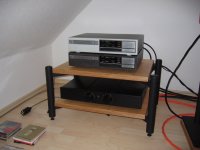
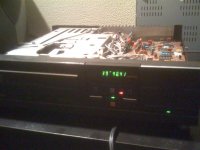
Finally, I finished my CD204 MKII hybrid project. During the last modification stage, the SAA7210 was damaged (I was not even working near it!?!) and it took the help of nanocamp to finally find the faulty chip. Since noon, it is spinning one of my favourite CDs and nicely breaking in.
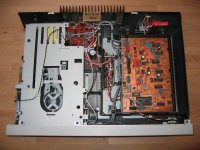
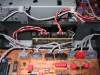
The mods I did to my CD204 MKII were:
• Adding Wima MKS2 as decoupling caps for the MSB and one down on the TDA1541,
• Installing some Neutrik RCA sockets and an IEC socket,
• Resoldering everything,
• Replacing all electrolytic capacitors on the supply board, servo board, decoder board, drive board and tray board with Panasonic FC,
• Replacing all tantalums and foils on the servo board with Wima MKS2,
• Replacing the output decoupling caps with Wima MKP10 and installing two different signal stealing points (after the I/V conversion and after the buffer),
• Damping the CDP with bituminised felt,
• Adding dedicated voltage regulators (LM317/337) for the op-amps (+/-12V), the TDA1541 (+5V, -6V), the SAA7220 (+5V) and the SAA7210 (+5V),
• Replacing the standard op-amps with OPA2132PA or THS4032 in sockets (with a Wima MKS2 between pin 4 and pin 8),
• Adding mica insulations to the voltage regulators and getting rid of several ground loops,
• Doing a switchable NOS modification,
• Deleting the muting and de-emphasis circuits with all associated components,
• And some more detail work.
Despite the new caps and only 4 hours of breaking in, the old Philips is already singing beautifully. During my listening tests, the SAA7220 was still installed and I only changed the signal stealing points. Directly after the I/V conversion, the sound is more open and detailed but misses a bit of the bass slam the CDP has got when the buffer is in use.
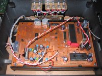
I added some pics of the modded CD204 MKII to give you a rough idea the work that went into it (the grey one is the MKII and the green one is my 14 bit CD204).
Best regards,
StefanAC
The mods I did to my CD204 MKII were:
• Adding Wima MKS2 as decoupling caps for the MSB and one down on the TDA1541,
• Installing some Neutrik RCA sockets and an IEC socket,
• Resoldering everything,
• Replacing all electrolytic capacitors on the supply board, servo board, decoder board, drive board and tray board with Panasonic FC,
• Replacing all tantalums and foils on the servo board with Wima MKS2,
• Replacing the output decoupling caps with Wima MKP10 and installing two different signal stealing points (after the I/V conversion and after the buffer),
• Damping the CDP with bituminised felt,
• Adding dedicated voltage regulators (LM317/337) for the op-amps (+/-12V), the TDA1541 (+5V, -6V), the SAA7220 (+5V) and the SAA7210 (+5V),
• Replacing the standard op-amps with OPA2132PA or THS4032 in sockets (with a Wima MKS2 between pin 4 and pin 8),
• Adding mica insulations to the voltage regulators and getting rid of several ground loops,
• Doing a switchable NOS modification,
• Deleting the muting and de-emphasis circuits with all associated components,
• And some more detail work.
Despite the new caps and only 4 hours of breaking in, the old Philips is already singing beautifully. During my listening tests, the SAA7220 was still installed and I only changed the signal stealing points. Directly after the I/V conversion, the sound is more open and detailed but misses a bit of the bass slam the CDP has got when the buffer is in use.
I added some pics of the modded CD204 MKII to give you a rough idea the work that went into it (the grey one is the MKII and the green one is my 14 bit CD204).
Best regards,
StefanAC
Attachments
Hello there!
Today I finally fixed my CD104!! I bought it about 5 years ago at a recycling-store. Because it needed to warm up every time I put the power on, I only used it for half a year or so.
I figured I would repair it sometimes, but since then it has been stored.
So, the day before yesterday i suddenly remembered this little machine and decided to plug it in and let it play for a while. It needed about 15 mins of warm up, but after that it played nicely again.
So, switched it on yesterday again but it just wouldn't start playing. After 4 hours of warming up it still went from -- 00:00 to --.
Well, thanks to this thread I read about the griplet thingies. So today i removed the solder, took the griplets out and connected it again with a piece of wire.
While I was at it, I also resoldered the larger parts in the power supply unit.
Now, it starts up directly! No warm up needed whoohoo It even plays CD's with holes in it without skipping or jumping hehe
Did notice some slight noise/distortion in the syllables, I don't know if it had this sound before. Could this be fixed by replacing caps? If so, which ones?
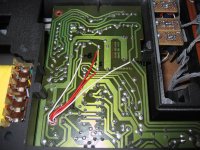
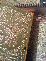
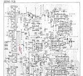
Also, I noticed there has been some work on this little player before. On the bottom side of the Servo PCB someone added a 1K resistor. See pic and artwork What's the purpose of this mod? Should I remove it?
Thanxs for all the info in this thread!!
Today I finally fixed my CD104!! I bought it about 5 years ago at a recycling-store. Because it needed to warm up every time I put the power on, I only used it for half a year or so.
I figured I would repair it sometimes, but since then it has been stored.
So, the day before yesterday i suddenly remembered this little machine and decided to plug it in and let it play for a while. It needed about 15 mins of warm up, but after that it played nicely again.
So, switched it on yesterday again but it just wouldn't start playing. After 4 hours of warming up it still went from -- 00:00 to --.
Well, thanks to this thread I read about the griplet thingies. So today i removed the solder, took the griplets out and connected it again with a piece of wire.
While I was at it, I also resoldered the larger parts in the power supply unit.
Now, it starts up directly! No warm up needed whoohoo
It even plays CD's with holes in it without skipping or jumping hehe Did notice some slight noise/distortion in the syllables, I don't know if it had this sound before. Could this be fixed by replacing caps? If so, which ones?
Also, I noticed there has been some work on this little player before. On the bottom side of the Servo PCB someone added a 1K resistor. See pic and artwork
What's the purpose of this mod? Should I remove it?Thanxs for all the info in this thread!!
Attachments
- Home
- Source & Line
- Digital Source
- Philips CD104 tweaks