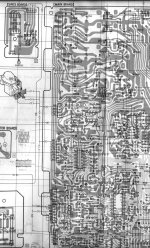
Here is the Circuit board of the CDP-40 please look at connector CP201
blue = LD Ground
yellow = LD Supply voltage
White = MD suppy voltage?
Red = MD ????
Any help to a newbie like me to mod the apc for the KSS-123A is very much welcomed...
blue = LD Ground
yellow = LD Supply voltage
White = MD suppy voltage?
Red = MD ????
Any help to a newbie like me to mod the apc for the KSS-123A is very much welcomed...
Attachments
Last edited:
I thought the Sony was OK ? why try and make a KSS123 fit. I thought it was the Nak you were trying to replace the pickup on.
Having established the pickups are different, there may well be other differences, perhaps in the coil/lens ballistics.
The servos are designed with the mechanical characteristics of the pickup in mind to ensure stability. I couldn't find much info on that (it's not something you generally need for service), but remember spending hours at Sony working through all the theory and getting to grips with Bode and Nyquist plots of the servo stability.
http://www.datarius.at/news/white_paper-PDF/wp_demystifying_the_drive.pdf
Here is the Circuit board of the CDP-40 please look at connector CP201
blue = LD Ground
yellow = LD Supply voltage
White = MD suppy voltage?
Red = MD ????
Any help to a newbie like me to mod the apc for the KSS-123A is very much welcomed...
Connector CP201:
blue = LD+PD Kathode - to GND (only one leg at the laser diode)
yellow = LD Anode - to C, Q202 ( regulated power output of APC);
E, Q202 about R211/210 from supply voltage - check line from R210)
White = MD - to 3, IC 201, non inverted input of comparator OP-Amp (APC regulated input)
Red = MD = connector of var. resistor - about voltage divider R202/201 to -Vee (in your case -5V)
Q202/201 and IC201 forms the APC circuit.
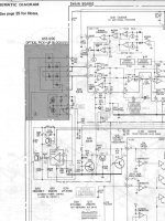
From different datasheets I have make a little overview of the individual APC circuits - perhaps this helps a little.
Mooly, thank you very much for this pdf URL:
http://www.datarius.at/news/white_paper-PDF/wp_demystifying_the_drive.pdf
where did you find it?
Attachments
Hello Mooly,
In the last three years, I spent weeks on the Nak trying perfect alignmmt.Never really succeeded, no matter the laser was old or new.
But the Sony is much better.
Could be because of the laser pickup, but assuming that the coils and optics of the KSS-122A and KSS-123A are the same, I would like to put the Sony´s electronics into the Nak and use ut with a KSS-123A.
The simple reason, why adpting the circuitry to KSS-123A: I have three KSS-123A as spares I bought then about 10 years ago.
Hallo Tiefbassuebertragung,
bedeutet / means
Connector CP201:
blue = LASERDIODE+PHOTODIODES A-D Kathode - to GND (only one leg at the laser diode- THEY ARE CONNECTED INTERNALLY ANYWAY)
yellow = LASERDIODE Anode - to COLLECTOR, Q202 ( regulated power output of APC);
EMITTER, Q202 about R211/210 from supply voltage - check line from R210)
White = MONITORDIODE - to PIN 3, IC 201, non inverted input of comparator OP-Amp (APC regulated input)
Red = MONITORDIODE = connector of var. resistor - about voltage divider R202/201 to -Vee (in your case -5V)
Correct?
All the best, Salar
Al the best
I was never satisfied, with the tracking abilities of the Nak.I thought the Sony was OK ? why try and make a KSS123 fit. I thought it was the Nak you were trying to replace the pickup on.
In the last three years, I spent weeks on the Nak trying perfect alignmmt.Never really succeeded, no matter the laser was old or new.
But the Sony is much better.
Could be because of the laser pickup, but assuming that the coils and optics of the KSS-122A and KSS-123A are the same, I would like to put the Sony´s electronics into the Nak and use ut with a KSS-123A.
The simple reason, why adpting the circuitry to KSS-123A: I have three KSS-123A as spares I bought then about 10 years ago.
Hallo Tiefbassuebertragung,
Connector CP201:
blue = LD+PD Kathode - to GND (only one leg at the laser diode)
yellow = LD Anode - to C, Q202 ( regulated power output of APC);
E, Q202 about R211/210 from supply voltage - check line from R210)
White = MD - to 3, IC 201, non inverted input of comparator OP-Amp (APC regulated input)
Red = MD = connector of var. resistor - about voltage divider R202/201 to -Vee (in your case -5V)
bedeutet / means
Connector CP201:
blue = LASERDIODE+PHOTODIODES A-D Kathode - to GND (only one leg at the laser diode- THEY ARE CONNECTED INTERNALLY ANYWAY)
yellow = LASERDIODE Anode - to COLLECTOR, Q202 ( regulated power output of APC);
EMITTER, Q202 about R211/210 from supply voltage - check line from R210)
White = MONITORDIODE - to PIN 3, IC 201, non inverted input of comparator OP-Amp (APC regulated input)
Red = MONITORDIODE = connector of var. resistor - about voltage divider R202/201 to -Vee (in your case -5V)
Correct?
All the best, Salar
Al the best
OK... mad idea... for test only.
How about connecting the LD via a multiturn pot and running with no APC just to see what happens and if it works. Scope the RF to get the power somewhere near, and keep it on the low side. And use a suitable decoupling network feeding the LD to eliminate any spike etc.
As to transplanting the Sony's electronics... what Servos and all ? ... into the NAK, well IMO that's a non starter.
Hello Mooly!
In fact, the Nak is more or less a Sony.
They use the same CX20109/CX2018/CX23035 Cipsets, same discmotors, have the same clock frequency and might probably been fed from the sane AC secondary voltages. System controllers should be adaptive. The only thing that might cause trouble will be the feed motors. The Nak uses a system with shaft, belt and gearwheel, the Sony a motor with screw drive and gearwheel. But I hope, with the shared chipsets, ratios will not differ lot.
All the best,
Salar
Hello Mooly!
In fact, the Nak is more or less a Sony.
All the best,
Salar
No. Definitely not.
Crucial to the similarity is the master processor/controller unit (MPU/MCU) with its custom specific software (unfortunately in most cases mask programable). The same slaves CX20109/CX2018/CX23035 compare to your SONY player and the same MCK frequency have no bearing for a possibility similarity.
Most people think, software differences there are only regarded operating instructions. That isn't true in most cases. There are still differences regarded the focus and
tracking behavior (to dirty discs or scratched discs e. g.).
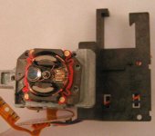
Another Idea: Put a very small amount low viscosity oil of the stud for the accutator unit (right of the collominator lens at the atteched photo) to reduction of mechanical friction.
Answer to post #25: I would say yes (E=Emitter, LD-Laser Diode, MD = Monitor/Photodiode).
Attachments
Last edited:
Hello Tiefbassübertragung!
I should oil the pole piece? As said, the Nak is not good in tracking, regardless if the laser is old or new. It is not defective. Just not as good as for example my 2nd Generation Toshiba XR-Z70.
And should a certain combination of chipsets not narrow down the programming of the controller units to a state, whre they should be interchangeable? If not, there is still the possibility of implanting the wole circuitry of the Sony except the D/A Board.
All the best, Salar
I wouldn't oil the lens bearing at all... this should be clean and dry.
Sticky lens bearings were a common problem with some early KSS pickups.
"Just came into my mind, maybe it is simpler to "redesign" the signal paths from the E-F diodes to CX20109 and amplification from CX-20108 to the coils in the nakamichi by using the sony values for resistance, capacitance , transistor equivalents...?"
And with the greatest respect,
Maybe it's simpler to call it a day")
The tracking on many early players was marginal at best... accept it's limitations and move on.
Sticky lens bearings were a common problem with some early KSS pickups.
"Just came into my mind, maybe it is simpler to "redesign" the signal paths from the E-F diodes to CX20109 and amplification from CX-20108 to the coils in the nakamichi by using the sony values for resistance, capacitance , transistor equivalents...?"
And with the greatest respect,
Maybe it's simpler to call it a day
The tracking on many early players was marginal at best... accept it's limitations and move on.
What would you say what is to do, if the Accutator on the floating stud firmly in place (because the used oil sometimes gummy)?I wouldn't oil the lens bearing at all... this should be clean and dry.
Sticky lens bearings were a common problem with some early KSS pickups.
In new condition there is a oil between bearing (stock jack - I dont know the exact name - even not in German) and the floating stud. Because both are made of metal (see to my last photo) I don't see a problem (except the risk of too much oil) and I have do this often in the last years without failure.
Whether it is the pole piece I can't say, but I don't believe it
An additional advice - below the accutator unit there is a plastic spring for the tracking compliance, which often is torn down. Therefore, the accutator isn't to remove without destroying the plastic suspension for tracking (even not after desolder the accutator coil leads).
By the way - Salar: which Nakamichi model you have in use? Perhaps you have mention anywhere and I have overlooked (maybe OMS7E?).
The mention bad tracking behaviour must be a fault (I have never heard about bad tracking behavior as typical character of Nakamichi OMS players). To find the fault, best way it is mostly, to buy from same model a second device to compare all oscillograms.
Last edited:
Hello Tiefbassübertragung!
No, nothing is faulty. My OMS-5EII / OMS-7EII is just weak on reading burned CD´s and reading small scratches in pressed CD´s.
Weak means:
I record a 20kHz Sine Tone and burn it on a CD, the Nak will play it with glitches, almost every half to one second, you hear glitches.
My other player, a Toshiba XR-Z70 from 1985, second generation, does better, no glitches at all when playing .
The Sony CDP-40 lies in between Tosh and Nak, still some glitches, but not as much as the Nakamichi. This is why I started the thread, to combine the KSS-123A with better servo electronics.
Probably, the laser pickup is the weakest part, but who knows, maybe the designers for the Nak´s servo circuitry had a bad day were forced to go for a cheaper option in Corcuit design and so on and so forth.
That´s what is all about, pushing the envelope.
I will probably put the RF-Amp Input circuitry directly under the laser pickup in the next weeks as a first step.
When aligning the Nak, it already matters, wether the lid (Gehaeusedeckel)is put on or off, maybe I get a small benfit from makingk the connections between the photosensors and the RF-Amp as short as possible.
Redesigning is simply beyond my knowledge
Greetings,
Salar
... and you´ll find out that CDr´s are in the lower range in a variation of Rf you get from commercial CdsCompare the RF output from a commercial CD and your burned CDR
CD-Roms make the focus signal swing like a sine wave.
On the other hand, many 25 year old Polygram - pressings I have (from the first CD-plant in Europe in Hannover), give a better RF than the Sony YEDS-18 Test-CD, proposed by Sony for setup.
I am using a choice of commercial CD´s for setup, been through this as well.
But first / second generation CD-players can play CD-Rs without a glitch, no doubt
Last edited:
Commercial disc (find a good "average" one) are fine for adjustments.
Any CD player "should" play CDR's... I find the RF is better at higher burn speeds ! which goes against a lot of thinking, but my scope, my CDR's and my Toshiba drive show otherwise.
And SACD... my Micromega won't play those, tries to focus, spins, and just keeps doing that. Look at the RF from the SACD in a first generation Philips and it looks similar to normal CD's...
hello Mooly,
same with me, I burned at slow speeds but came back to safer DAT.
But do a check like I did, if you have a First - third generation player, burn a 20kHz signal and ckeck for clicks during playback.
Any advices for moving the RF-Amp underneath the laser pickup? Shielding of the RF-Amp IC needed?
All the best,
Salar
Hello Tiefbassübertragung!
No, nothing is faulty. My OMS-5EII / OMS-7EII is just weak on reading burned CD´s and reading small scratches in pressed CD´s.
Weak means:
I record a 20kHz Sine Tone and burn it on a CD, the Nak will play it with glitches, almost every half to one second, you hear glitches.
My other player, a Toshiba XR-Z70 from 1985, second generation, does better, no glitches at all when playing .
The Sony CDP-40 lies in between Tosh and Nak, still some glitches, but not as much as the Nakamichi. This is why I started the thread, to combine the KSS-123A with better servo electronics.
Probably, the laser pickup is the weakest part, but who knows, maybe the designers for the Nak´s servo circuitry had a bad day were forced to go for a cheaper option in Corcuit design and so on and so forth.
That´s what is all about, pushing the envelope.
I will probably put the RF-Amp Input circuitry directly under the laser pickup in the next weeks as a first step.
When aligning the Nak, it already matters, wether the lid (Gehaeusedeckel)is put on or off, maybe I get a small benfit from makingk the connections between the photosensors and the RF-Amp as short as possible.
Redesigning is simply beyond my knowledge
Greetings,
Salar
There is always a benfit to keep the signal to noise ratio as low as possible arround the connections between the photosensors and the RF-Amp input (e. g. screening wires and/or wire length as short as possible).
If your RF-signal looks sharp at your scope, the reason for your effects must be an other.
At whole - where are an extrem wide range of influences to the quality of RF signal - e.g.:
- press/burn quality (sharpness of tracing curves)
- tolerances by wave length by your laser diode (780-785nM, level)
- tolerances by the reflective properties of the compact disc (e.g. sometimes 780nM for max RF-Level, sometimes the reflective optimum by lower or higher values of wavelength - also independend of the individual tolerance of your laser diode)
- mechanical tolerances of lens, prisma, fotodiode matrix (OPIC) position
- quality of whole hardware design (circuit and layout/GND-management)
- quality of softwaredesign, determined mainly in a case of edge the sample behavior (still possible reading of the pits or not, how fast comes the "mute" mode and many many more)
To modify a cd player (outside of S-P/DIF-DAC unit and MCK oscillator unit for jitter reduction) is a real challenge, because there are no basic descriptions with corresponding modification advices - as I know.
Additional I don't know professional tuning companies like
Welcome to Trichord Research
which do this.
But if I'm wrong, please let me know. It would be highly interesting to know, how I find a nacked MCU/MPU for compact disc player and how I create a new progammable software to optimize the error correction, the tracking behaviour and the focus behaviour for slightly warped compact disc e. g. - for a professional programmer resp. hacker an easy exercise, I think.
Last edited:
hello Mooly,
same with me, I burned at slow speeds but came back to safer DAT.
But do a check like I did, if you have a First - third generation player, burn a 20kHz signal and ckeck for clicks during playback.
Any advices for moving the RF-Amp underneath the laser pickup? Shielding of the RF-Amp IC needed?
All the best,
Salar
RF amp underneath lol, get something that uses the CDM12.4
I have no issues with playability of CDR's... haven't tried what you suggest re 20k, but can't really see why that should be a problem.
The music will mask glitches. 20kHz, you will not be able to hear ( I am able to hear up to to around 16kHz), but you wil hear, when the error correction fails.
And why not putting the RF-Amp underneath, to my knowledge, all designs since the early nineties work like this? KSS-240A is one of them for sure.
Shielding would be easier, but the wires have to be very flexible...
And why not putting the RF-Amp underneath, to my knowledge, all designs since the early nineties work like this? KSS-240A is one of them for sure.
Shielding would be easier, but the wires have to be very flexible...
- Status
- This old topic is closed. If you want to reopen this topic, contact a moderator using the "Report Post" button.
- Home
- Source & Line
- Digital Source
- KSS-122A and KSS-123A - Are they Interchabgeable?