Lets not loose track on the interesting small signal transformer topic, guys .
Here is my today's measurement of one I have available.
Its a 1:1 purchased in Germany way back and though I do not really know its origin, I have a strong feeling it possibly could be a re-labelled Amplimo TM8 – dunno.
Measurement was done for convinience directly with my soundcard which specs as
source impedance 100 Ohm balanced
load impedance 20kOhm balanced
STEPS was calibrated so we see that the transformer was driven by ~ 1Vrms

We can see here as well that 3rd order is dominating – here all the way up to 10kHz where 2nd takes over
")
Comparing to Gary's Lundahl we see that this one performs ~30dB worse at around 1kHz – I guess it costs only 1/10 the Lundahl tho...
http://www.diyaudio.com/forums/multi-way/15943-behringer-dcx2496-digital-x-over-46.html#post2042289
Michael
Here is my today's measurement of one I have available.
Its a 1:1 purchased in Germany way back and though I do not really know its origin, I have a strong feeling it possibly could be a re-labelled Amplimo TM8 – dunno.
Measurement was done for convinience directly with my soundcard which specs as
source impedance 100 Ohm balanced
load impedance 20kOhm balanced
STEPS was calibrated so we see that the transformer was driven by ~ 1Vrms
We can see here as well that 3rd order is dominating – here all the way up to 10kHz where 2nd takes over
Comparing to Gary's Lundahl we see that this one performs ~30dB worse at around 1kHz – I guess it costs only 1/10 the Lundahl tho...
http://www.diyaudio.com/forums/multi-way/15943-behringer-dcx2496-digital-x-over-46.html#post2042289
Michael
Last edited:
Hi Michael,
Have you run a baseline loop back test with Steps? The rise in distortion above 4K is an artifact of my sound card so the distortion of the Lundahl is better than my measurement system...
With the noise floor where it shows in Steps, I suspect that Steps is running in 16 bit mode. I've not had time to look and see if the resolution is configurable in Steps.
Gary
Thanks for the measurement Michael.
I have seen a rise in 3rd order distortion in the bass for small transformers. Thats one reason you can't go too small.
But otherwise the harmonics track well. Yes, odd order is dominant, but everything seems to track well together.
I wish I could get Steps to work for me. I always get glitches, but never at the same place. This results in nasty distortion spikes. No other software does that on my setup. Might have to try a different computer.
Gary. I did try balanced into the DUO soundcard and got somewhat better results - thanks! I was going to post them, but then saw that I had done different scales and FFT values. =( Will do over. Mostly what I'm seeing is that the transformer output is much cleaner in the top end than the DCX active output. Harmonically speaking.
Have you run a baseline loop back test with Steps? The rise in distortion above 4K is an artifact of my sound card ..
Well I did - but looking twice sometimes isn't enough.
Thanks for pointing there.
I checked and found that my setting in STEPS was on 32 bit – no good - inserting line drives feeding the adjustable mic-input plus checking ground connects brought another improvement...
###########
Repeated my measurement under optimized conditions.
To allow for some further interesting insights I added measurements on –20dBV and on –40dBV
Michael
Last edited:


Looking at this row of measurements we see that the increase after the slope clearly have been from artefact's.
What else we see is that the 3rd order - obviously form saturation – fully dominates distortion.
Interestingly this plays a big role up into the voice region – depending on signal level.
Also it becomes clear that this very transformer is of no adequate performance on line levels – but possibly could be OK for mic levels
Michael
Last edited:
Thanks for the measurement Michael.
.
You are welcome
.
I wish I could get Steps to work for me. I always get glitches, but never at the same place. This results in nasty distortion spikes. No other software does that on my setup. Might have to try a different computer.
.
Have you checked
- buffer size ?
- sampling rate being the same for STEPS and your soundcard ?
Michael
Last edited:
Back again – found a small mistake in one measurement and hence deleted former posting
########
Here is another interesting measurements of a ~ 1:6 small signal transformer made by WSW, I had at hand.
This is a rare piece of ancient Austrian PRO audio gear, manufactured by Vienna's "Wiener Schwachstrom Werke" - later on, taken over by Siemens Kangfilm to my knowledge.
http://www.tube-classics.de/TC/Klangfilm/Klangfilmhistory.htm
This transformer is roughly double the size of the previous one :
22mm x 28mm x 34mm (versus 20mm x 24mm x 24mm)
Anyway – lets have a look – it performs quite different :
Fed by 1Vrms:


Fed by 0.1Vrms


It is interesting that this one, compared to the former one, seems to perform way better in the lower frequency department.
Fed by 100mV, distortion is down to ~ 24bit territory, up form ~200Hz – not that bad !
Though this small signal transformer clearly too isn't suitable for 1Vrms line levels, it already performs quite well at 100mV level – or even slightly higher.
Frequency response seems to be excellent for both transformers IMO.
Wonder how different core materials behave in the lower and upper FR range, so I am looking forward to the measurements of better known (and available) device.
Michael
########
Here is another interesting measurements of a ~ 1:6 small signal transformer made by WSW, I had at hand.
This is a rare piece of ancient Austrian PRO audio gear, manufactured by Vienna's "Wiener Schwachstrom Werke" - later on, taken over by Siemens Kangfilm to my knowledge.
http://www.tube-classics.de/TC/Klangfilm/Klangfilmhistory.htm
This transformer is roughly double the size of the previous one :
22mm x 28mm x 34mm (versus 20mm x 24mm x 24mm)
Anyway – lets have a look – it performs quite different :
Fed by 1Vrms:
Fed by 0.1Vrms
It is interesting that this one, compared to the former one, seems to perform way better in the lower frequency department.
Fed by 100mV, distortion is down to ~ 24bit territory, up form ~200Hz – not that bad !
Though this small signal transformer clearly too isn't suitable for 1Vrms line levels, it already performs quite well at 100mV level – or even slightly higher.
Frequency response seems to be excellent for both transformers IMO.
Wonder how different core materials behave in the lower and upper FR range, so I am looking forward to the measurements of better known (and available) device.
Michael
Cool work. I'm a little unclear on the graphs, which one is what level. But I do see the same sorts of things I've been measuring. Smaller transformers have more 3rd harmonic in the low end. And of course that rises with signal level.
That is an advantage that opamps seem to have - less distortion in the low end than most transformers. From 1K up is another story.
I'll keep working with Steps- maybe buffer settings will do it.
That is an advantage that opamps seem to have - less distortion in the low end than most transformers. From 1K up is another story.
I'll keep working with Steps- maybe buffer settings will do it.
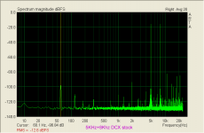
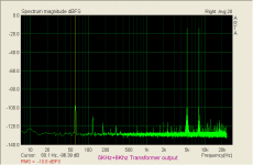
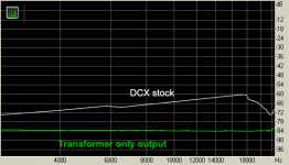
Yes Andrew, pretty much. At least at the top end. But the stock output has less distortion than the transformers in the low end of the spectrum. The transformers I tested have a 3rd harmonic that rises at lower frequencies. You will see that in some of the graphs below.
I'm curious about this 3rd order harmonic, because I measured a number of transformers last year and these showed very little distortion rise at the bottom end. And I don't know why the difference. I'll have to figure it out.
These plots show how the DCX stock output has a distortion that rises with frequency and the transformer has a distortion that drops with frequency. To my ear, this must be why I feel that the transformers remove a lot of digital glare or brittleness that I don't like. The swept FR is so close between these two there is no point to post it.
I'll try to figure out why I'm now seeing H3 distortion at the bottom end with the transformers that I did not measure last year.
Attachments
Cool work. I'm a little unclear on the graphs, which one is what level..
Thanks.
Concerning plot level, simply refer to the schematic above each plot. You see "the chain of signal flow" from left to right (no connections shown - but markers instead). Each plot is correctly calibrated.
Basically the soundcard output was (digitally) attenuated to get the 1V rms at first hand – which in all measurements is kept constant.
To perform measurements at attenuated levels (–20dB) I simply inserted a differential voltage divider that keeps its source impedance the same 100 Ohm as the soundcard's output.
If you cascade that differential voltage divider you get attenuation of –40dB (well roughly).
The setup limits are always shown first by a simple loop back measurement (no DUT inserted) to confirm validity.
Measurement is performed by processing the transformers output through a line receiver / line driver pair – and then feeding the mic-in of the soundcard.
For measurement of –20dB (100mVrms at transformer-IN) the mic gain was turned up by ~20dB - for measurement of –40dB (10mVrms at transformer-IN) the mic gain was turned up by ~40dB
This somehow complex procedure provided the cleanest and most consistent results over the wide range of levels.
At any change of mic-gain, STEPS was re-calibrated of course.
I'll keep working with Steps- maybe buffer settings will do it.

One other thought – in case you have a setting for "internal" or "external" clock – check "internal"
Michael
Last edited:
Hey Michael.
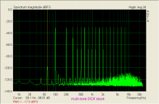
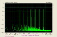
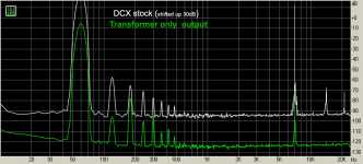
That 3rd chart is the IMD sweep as done by RightMark. I don't know much about the measurement, the RMAA doc doesn't tell me much. The far right chart is 60Hz and 7KHz IMD.
All the measurements in ARTA were done with the digital signal at -6dBFS. That was to prevent overdriving anything. I did my best to adjust the soundcard inputs to -6dBFS as well. So a sort of "digital unity gain." Obviously the stock DCX outputs had to be (analog) attenuated much more than the simple transformer outputs to reach that level. Similar to what you are doing.
So the output of the DCX was never full scale, but -6dB. Driven with a digital input only.
Not really sure why ARTA places the noise floor below -120dB. That should not be possible working in 16bits, as I was. RightMark tells me the noise floor is about -94dB.
- Home
- Source & Line
- Digital Line Level
- Behringer DCX2496 digital X-over