I'm sorry, but there is a huge change in the contour from the driver to the horn and a significant amount of diffraction will occur at this point. It is a diffraction horn in my book.
An oval shouldn't do too bad in the diffraction department should it? Maybe still not as good as a circular one?
Dan
Its not a mis-match in area that concerns me, it's a mismatch in the slope of the walls that is more important and the slope changes are large. Area changes are also a concern and that device has both. Minimum diffraction occurs when BOTH the area and wall slope change in the most gradual way possible (and of the two the slope is the more important) and this is true all the way from the diaphragm to the mouth.
Its not a mis-match in area that concerns me, it's a mismatch in the slope of the walls that is more important and the slope changes are large. Area changes are also a concern and that device has both. Minimum diffraction occurs when BOTH the area and wall slope change in the most gradual way possible (and of the two the slope is the more important) and this is true all the way from the diaphragm to the mouth.
Interesting. I've got to read that a few more times before it sinks in.

OK, got it.
Dan
Last edited:
I don't agree with putting the speakers on the ground because its not the correct conditions. The errors are all highly dependent on the loudspeaker systems specifics so they are not tractable. Free field on a stand is a much more accurate way to do things.
If you mean "on the ground" as in facing forward, then I agree. But if you mean "on the ground" facing up, then I don't. I've done all sorts of measurements, and I've found that a speaker on its back facing up gives great results for finding nulls. Since we're looking at stuff around 1kHz, a gated measurement is just fine and that means it can be done indoors. You can put the speaker in free space but it takes more effort and isn't required.
This, of course, assumes crossover in the ~1kHz region where woofer and (90°) tweeter directivity match in the horizontal plane. Other types of systems may not work this way, for example, those crossed where the pattern is wide, etc. But for a DI-matched two-way, the indoors gated approach works very well and is pretty easy.
I like anechoic (free field) measurements for full range, because only those conditions show accurate response at low frequency. But for visibility into the 1kHz range, the only real condition that needs to be met is the nearest boundaries can't be closer than the gating. With the directivity narrowing to approximately 90 degrees, the rear reflection from lying on the back isn't a real big deal, certainly not enough to impact the location or strength of the nulls.
Last edited:
I don't understand the main difference from "outdoor measurements" with microphone suspended at a standard distance from the ground, that you say is problematic (in respect to the specifics/box?).I don't agree with putting the speakers on the ground because its not the correct conditions. The errors are all highly dependent on the loudspeaker systems specifics so they are not tractable. Free field on a stand is a much more accurate way to do things.
http://www.listeninc.com/PDFs/technote_loudspeaker_performance_at_low_frequencies.pdf
I don't understand the main difference from "outdoor measurements" with microphone suspended at a standard distance from the ground, that you say is problematic (in respect to the specifics/box?).
http://www.listeninc.com/PDFs/technote_loudspeaker_performance_at_low_frequencies.pdf
If the system is imbedded flush with the ground then its basically an infinite baffle, no problem. But if its an enclousre setting above the ground then there is. That's because of the wave that goes back and reflects off the ground and arrives delayed from the direct one. This causes all kinds of problems, which depend on the specifics - box dimensions, frequency range, polar response of the system, etc. etc.
Thats a good paper on the subject by the way and precisely what they suggest is what I do and recommend.
Last edited:
Why would a coaxial inherently have "lousy" pattern control? That makes no sense.This is why I don't approve of coax (except in space critical apps.) - no vertical lobes, but lousy horizontal pattern control.
KEF 207/2
Gradient Revolution - that at least equaled your Summa in your own conducted listening tests
What exactly is "lousy" about the horizontal pattern control?
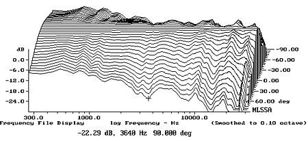
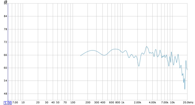
Look at these graphs. Same drivers. One 15" coax driver. The next with the same tweeter taken out and placed in a cheap WG from parts express. I'll do one right after the other in 11.25 degree changes from 0 degrees out to 45 degrees. I'm not saying this is going to be the case with all coaxials. I bet Genelec's don't do that and possibly even Tannoys'.
15" Coax on axis:
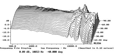
Same drivers, but tweeter on cheap waveguide on axis:
(sorry, I tried to tighten the window on the coax to smooth it's response some. Obviously didn't work. and the graph dimensions also make the coax look worse)
coax 11.25 off:
again same drivers but tweeter in WG 11.25 off:
coax 22.5 off:
WG 22.5 off:
coax 33.75 off:
WG 33.75 off:
coax 45 off:
WG 45 off:
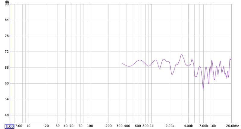
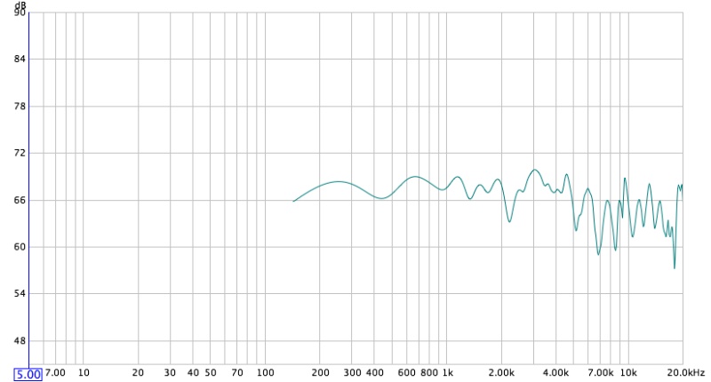
I wish the graph periods were the same, but I changed them b/c I can't measure Bass when gating anyway. I didn't realize the coax measurements I had were still w/ the different periods. The coax doesn't look that much worse overall than the cheapy waveguide, just different and much less smooth overall. Maybe it's a wash? The coax definitely sounds brighter in the room, and more diffuse. It's harder to pick out what's going on with the coax even though it's brighter.
What do you guys see?
Dan
15" Coax on axis:
Same drivers, but tweeter on cheap waveguide on axis:
An externally hosted image should be here but it was not working when we last tested it.
(sorry, I tried to tighten the window on the coax to smooth it's response some. Obviously didn't work. and the graph dimensions also make the coax look worse)
coax 11.25 off:
again same drivers but tweeter in WG 11.25 off:
An externally hosted image should be here but it was not working when we last tested it.
coax 22.5 off:
WG 22.5 off:
An externally hosted image should be here but it was not working when we last tested it.
coax 33.75 off:
An externally hosted image should be here but it was not working when we last tested it.
WG 33.75 off:
An externally hosted image should be here but it was not working when we last tested it.
coax 45 off:
An externally hosted image should be here but it was not working when we last tested it.
WG 45 off:
An externally hosted image should be here but it was not working when we last tested it.
I wish the graph periods were the same, but I changed them b/c I can't measure Bass when gating anyway. I didn't realize the coax measurements I had were still w/ the different periods. The coax doesn't look that much worse overall than the cheapy waveguide, just different and much less smooth overall. Maybe it's a wash? The coax definitely sounds brighter in the room, and more diffuse. It's harder to pick out what's going on with the coax even though it's brighter.
What do you guys see?
Dan
Last edited:
The problem with coaxials having horn loaded tweeters firing through the center of the midwoofer's pole piece is the short horn is really a compromized stub, too small to get good pattern control.
Back to drivers stacked vertically on the baffle, when one wants to find the position of the vertical nulls, I strongly suggest the procedure shown in the video below:
With the loudspeaker on its back, the ceiling is eight feet away and walls are presumably further. That's far enough that boundary reflections manifest themselves well below the frequency range where the nulls are. The floor is closer, yes, but we aren't really concerned with the rear wave when trying to find the location of the nulls. If you put the speaker on a stand, then my experience has been that the floor and ceiling reflections are often confusingly close to the frequency range of the nulls you're looking for.
When designing the crossover, the phase between drivers and their physical positions sets the position of the forward lobe and vertical nulls, and it is important to be able to quickly and easily identify them. It's convenient to make these measurements indoors, and the procedure shown above works perfectly for that. There are others, sure, so whatever works for you is good. This has just proven to be the most reliable for me, when I want to examine the position of the nulls, which tells me a lot about the crossover.
The next phase of design should include anechoic measurements with a full set of polars. This is where you get accurate full range response charts. But for the initial design phase where you're determining the position of the forward lobe and vertical nulls, a series of pseudo-anechoic measurements with the speaker on its back is just fine. You're really just looking for the deep notches in the crossover region, after all, and those will not be anywhere near the self-interference notches from lying on their back. The self-interference notch will be much lower in frequency, and you can easily disregard it.
The problem with coaxials having horn loaded tweeters firing through the center of the midwoofer's pole piece is the short horn is really a compromized stub, too small to get good pattern control.
That's for sure in general. I'd like to see measurements from the Tannoy and Genelec designs.
Dan
I usually measure polars with the speaker laying on its back, facing upward towards a microphone on a boom, using a protractor to place the microphone at the desired angles.
My opinion on coverage is that response should be uniform across a horizontal arc of 90 degrees, and uniform across a vertical arc of at least 40 degrees but not more than about 60 degrees. I also think the center of the forward lobe should be roughly along the baffle normal, with the vertical nulls basically equidistant above and below the speaker.
The reason I like this roughly 90x40 to 90x60 pattern is the 90 degree horizontal pattern is very convenient for home placement, making a useful coverage area with nice large seat-to-seat coverage. The desired vertical pattern is large enough to be useful, allowing the listeners to sit in a clean forward lobe at a reasonable listening distance, but small enough to limit ceiling slap at HF.
Related threads:
Thanks again for this Wayne! Must truly be a labor of love. Between the help from you and Dr. Geddes, I might be able to eventually build a worthwhile speaker.
Dan
A typically terrible coaxial speaker.What do you guys see?
Nothing inherent about the format (as incorrectly stated by Earl and Wayne, who sell non-coaxials) and everything to do with poor implementation/construction.
Still waiting on comments on the data I posted...and what is "lousy" about the pattern control...as well as listening panel subjective perception of this "lousy" control vs "not so lousy" control (JBL/Summa), in an actual living room, rather than cyberspace speculation and chatting.
cheers,
AJ
I see the cheapo waveguide holding constant-directivity pattern control in the highest octave and the co-ax having essentially none.What do you guys see?
We've been here before with the Eminence Beta 10CX in the "Copper Speaker" thread....

I wasn't getting notified of these replys. This forum sometimes does that if there is a flury of posts.
I was refereing to coax Waveguides, not coaxial in general, I should have been more specific. Yes, a coaxial tweeter could be made to perform better than a seperate tweeter and woofer or midrange. It is the waveguide issue that I was talking about. In general there is no problem getting a piston tweeter close enough to the other driver such that the lobing is not an issue, but it IS a problem with horns and waveguides, so my comment was specfic to those. All the examples of "good" coaxs are not horns, but then that technology is not easy to do and you still have the issue with directivity control - it is what the outer drivers cone is - and thermal handling of the small tweeter. So it has its advantages for lower powered systems. The Genelec approach looks very good, I have to say. Genelec is an admirable company if you can afford them. My speakers are much cheaper. And it's all my work that they are using - I know that because they told me so.
I was refereing to coax Waveguides, not coaxial in general, I should have been more specific. Yes, a coaxial tweeter could be made to perform better than a seperate tweeter and woofer or midrange. It is the waveguide issue that I was talking about. In general there is no problem getting a piston tweeter close enough to the other driver such that the lobing is not an issue, but it IS a problem with horns and waveguides, so my comment was specfic to those. All the examples of "good" coaxs are not horns, but then that technology is not easy to do and you still have the issue with directivity control - it is what the outer drivers cone is - and thermal handling of the small tweeter. So it has its advantages for lower powered systems. The Genelec approach looks very good, I have to say. Genelec is an admirable company if you can afford them. My speakers are much cheaper. And it's all my work that they are using - I know that because they told me so.
I'm curious about this too. The coax drivers I know have the same vertical as horizontal pattern. How is the control worse than in the horizontal direction?
Take a look a a UREI Coax. On axis great, horizontal OK. Vertical is terrible. You have to be right on axis. I use an 811C as my center channel in my HT set-up.
JBL Technical Notes Volume 1 Number 15 - Lansing Heritage Forums
It is a diffraction horn in my book.
How much of a deviation from a circular toward an ovoid cross section, in your opinion, would be tolerable before an ideal areal cross section from a HOM perspective becomes a 'diffraction horn', or at least suffers significant compromise from a HOM perspective?
In general there is no problem getting a piston tweeter close enough to the other driver such that the lobing is not an issue, but it IS a problem with horns and waveguides
The Iron Lawbreaker, as I have previously described in this thread, is an example of a real world solution to this 'problem'. In fact, it takes a fair amount of concentration from any normal listening position to perceive a difference in azimuth for the LF vs HF source of its output since vertical and horizontal lobing and dispersion do not suffer from anomalies through the xover region.
Last edited:
- Status
- This old topic is closed. If you want to reopen this topic, contact a moderator using the "Report Post" button.
- Home
- Loudspeakers
- Multi-Way
- Importance of vertical polar response