Bob, it could just be me, but Im quite happy with that datasheet, tells me enough of all the parametres of interest.
Tell me which spice models you looking for, I might have some that are of interest ,they have models but only release if you a regurlar buyer, from Sanyo Ive been able to get them to make me some for transistors I wanted and with a large purchase they supplied the models but in this they are very strict, their bussiness ethics differ quite a bit from ours. They state that spice models give out too many info on the part which doesnt make a lot of sense to me, surely one cannot make copies based on spice parameters.
As for the maths I think its important, only way we going to get better models, Andys output device models are the most accurate around this forum or any other for that matter, I dont use anything else. Ive spent some time modifying some models to closer reflect datasheet and I can tell you its not easy at all and very time consuming, a litttle change here to get this curve closer to datasheet and something else goes completly wrong with another parameter, Ive given up, I simply dont have the time.
Tiefbassuebertr, those mospec parts I wouldnt use, the chinese manufactured devices Im sorry to say are very inferior, they might have improved in the meantime but the first time I cracked a transistor of theirs open I was horrified. They also dont make up datasheets, they just supply a copy of the original manufactureres datasheet, scary, how do they know their parts are conforming to datasheet.
Hi Homemodder,
Can you send me the SPICE models for the 2SC3281 and its complement?
You are right about Andy's models, and his work shows how poor some examples of manufacturer's models are. I have also spent many hours trying to create accurate SPICE models of power transistors and know how difficult it is. In some cases, parameters have to be measured in the lab at collector currents well below where the datasheet plots them.
Cheers,
Bob
Wahab,
It was a little unclear if you were also referring to beta droop of the MJL3281 devices in the post above, but I did do some measurements of beta on the MJL3281 at very low collector current to examine low-current beta droop. Here are the results, with Ic in mA on the left and beta on the right:
0.1 mA: 59
1.0 mA: 74
10 mA: 88
100 mA: 100
300 mA: 107
I consider these to be very good numbers for low-current beta droop in a large power transistor.
Cheers,
Bob
thank you ,bob, i see that you gave some more digging about the subject..
yes, the figures are quiete good...
i ll dig the thing to compare with the nippon products..
about the models, i ve got many for the same device...
i did took the ones that seems to be on par with the datasheet..
as modern bjts, 2SA1943/2SC5200 are fine. the simulator innacuracy is
not enough to explain the gap between those and onsemi s MJLs...
as noted by homemoder, i suspect the japanese to be secretives
fear that the others manufacturer would find the parameters that were enhanced by studying the models...
*QS2SC3281 MCE 5/13/95
*Si 150W 200V 15A 30MHz pkg:TO-247 2,1,3
.MODEL 2SC3281 NPN(IS=10.000E-15 BF=155.65 VAF=100 IKF=9.2028 XTB=1.5
+ISE=54.325E-15 NE=1.3056 BR=10.787 VAR=100 IKR=1.8561 ISC=106.69E-15
+NC=1.6728 RC=26.745E-3 CJE=2.0000E-12 CJC=534.41E-12
+MJC=.33333 TF=8.0821E-9 XTF=3.1968 VTF=21.461E-3 ITF=169.59 TR=187.91E-9 )
*QS2SA1302
*Si 150W 200V 15A 30MHz pkg:TO-247
.MODEL 2SA1302 PNP( IS=21.479E-12 BF=136.48 VAF=100 IKF=19.980 ISE=21.504E-12
+NE=1.3784 BR=329.48 VAR=100 IKR=19.980 ISC=4.3670E-9 NC=1.4264 RC=93.301E-3
+CJE=755.31E-12 MJE=.33333 CJC=1.1417E-9 MJC=.33333 TF=1.2802E-9 XTF=10 VTF=10
+ITF=1 TR=10.000E-9)
.SUBCKT QSC3281DA 1 2 3
* TERMINALS: C B E
* 200 Volt 15 Amp SiNPN Power Transistor 12-03-1991
Q1 1 2 3 QPWR .67
Q2 1 4 3 QPWR .33
RBS 2 4 9.5
.MODEL QPWR NPN (IS=1.63P NF=1 BF=150 VAF=254 IKF=12 ISE=1.34N NE=2
+ BR=4 NR=1 VAR=20 IKR=16.5 RE=22.1M RB=4 RBM=.4 IRB=5.556U RC=4.84M
+ CJE=481P VJE=.6 MJE=.3 CJC=312P VJC=.22 MJC=.2 TF=5.33N TR=204N)
+ XTB=1.5 PTF=120 XTF=1 ITF=9.6)
.ENDS
.SUBCKT QSA1302DA 1 2 3
* TERMINALS: C B E
* 200 Volt 15 Amp SiPNP Power Transistor 12-03-1991
Q1 1 2 3 QPWR .67
Q2 1 4 3 QPWR .33
RBS 2 4 9.5
.MODEL QPWR PNP (IS=1.63P NF=1 BF=130 VAF=254 IKF=11 ISE=1.34N NE=2
+ BR=4 NR=1 VAR=20 IKR=16.5 RE=12.1M RB=4 RBM=.4 IRB=5.556U RC=4.84M
+ CJE=1.09N VJE=.6 MJE=.3 CJC=708P VJC=.22 MJC=.2 TF=5.33N TR=204N)
+ XTB=1.5 PTF=120 XTF=1 ITF=9.6)
.ENDS
.MODEL Q2SC5200 NPN (
+ IS =4.3031E-12
+ BF =152.1
+ NF =1.0
+ BR =6.155
+ NR =1.028
+ ISE =1.3924E-11
+ NE =1.5
+ ISC =2.7542E-11
+ NC =1.95
+ VAF =60.0
+ VAR =6.51
+ IKF =10.8637
+ IKR =0.1585
+ RB =2.47
+ RBM =0.02
+ IRB =0.08
+ RE =0.04
+ RC =0.015
+ CJE =5.8111E-9
+ VJE =0.6506
+ MJE =0.3357
+ FC =0.5
+ CJC =6.4394E-10
+ VJC =0.5
+ MJC =0.3966
+ XCJC =0.7624
+ XTB =1.0445
+ EG =1.1663
+ XTI =3.0 )
.MODEL Q2SA1943 PNP (
+ IS =3.5476E-11
+ BF =159.9
+ NF =1.0
+ BR =25.75
+ NR =1.011
+ ISE =2.5119E-10
+ NE =2
+ ISC =7.9433E-11
+ NC =1.37
+ VAF =60.0
+ VAR =11.07
+ IKF =2.8370
+ IKR =0.3548
+ RB =2.74
+ RBM =0.0381
+ IRB =3.6308E-3
+ RE =0.06
+ RC =0.01
+ CJE =4.1783E-9
+ VJE =0.6354
+ MJE =0.3374
+ FC =0.5
+ CJC =1.1383E-9
+ VJC =0.5
+ MJC =0.3699
+ XCJC =0.7624
+ XTB =1.5306
+ EG =1.1751
+ XTI =3.0 )
regards, wahab
Honestly I have no idea where the notion that 2N3055 derived power BJTs were developed for switching applications. Onsemi/Motorola themselves have made a number of BJTs specifically for this purpose.
It is actually fairly easy to spot a switching power BJT, by a relative lack of SOA at conditions where it routinely needs to be for linear applications. A look inside the case will often also show a comparatively smaller die - no wonder since you want to keep the capacitances low.
Simply put, the 'old' 4MHz Ft power BJTs were developed for linear regulators, amplifiers and the like, but usually for servo amps and similar where a 200kHz power bandwidth is generally NOT expected. A look at the SOA curves is the clue - these slow devices are very sturdy. Amongst all the types quoted in this thread, only some 3-diffused offerings from Allegro/Sanken come close, while retaining lower beta droop and higher Ft - but this is actually similar technology.
However, disregarding these 'old' devices (and BTW, technically speaking, they are derivatives of the 2N3773, also in it's lower voltage guise known as the 2N3055H) because they are 'slow' is not a good idea. Basically, the increased sturdyness of the output stage places higher demands on the driver stage - so does the increased beta droop. In the old days, the simple, but not exactly cheap way of dealing with this, was to put several pairs in parallel even though the SOA requirements would not demand it (and usually using tripple darlington drivers). The point was, to keep the current per device inside the high beta region - but at the cost of higher input capacitance, higher price. In addition, this policy would provide for a beefy output stage that would drive difficult loads reliably, but with increased distortion.
Ironically, the very devices touted as 'best' in this thread use the very same approach but on the chip scale - they are also made up of paralleled cells or their structures are distributed along a large area, in essence, forming an array of parallel transistors - with exactly the same goal in mind.
Also ironically, when one speaks of 'more modern Japanese devices' we are really talking about derivatives of technologies that were already commercially used as far back as 30 years ago. Japanese discrete semis went from 2N3055 types to 2SA1302 in a matter of a decade, which was truly a quantum leap. Alongside, lateral MOSFETs and before them, vertical FETs (SITs) were developed - in the latter case it's even become forgotten knowledge. In the last 25 years, linear power BJTs have only progressed perhaps 10% of this initial leap, so looking at the list at the beginning of this thread, from that standpoint, save for the original 2N3055 - or more accurately, 2N3773 developements, all the rest are variations on a theme.
It should be also noted that while some companies make 'copies' - i.e. equivalent devices under license, or near equivalent through joint vo-developement, others make near-equivalents, based in their existing technology and developments thereof. Onsemi MJL parts are precisely this kind of a device, where high beta, low beta droop, and high Ft were attempted to be combined with superior SOA. Those knowledgeable in semi technology will already know that fast devices tend to have worse SOA, so if you want to get the best of all worlds, some things will be optimized - one of them being, what a resonable ft is in audio applications. Of course, one must hope that as a result, you do not get a device which is equally bad in any application, as opposed to equally good")
It is actually fairly easy to spot a switching power BJT, by a relative lack of SOA at conditions where it routinely needs to be for linear applications. A look inside the case will often also show a comparatively smaller die - no wonder since you want to keep the capacitances low.
Simply put, the 'old' 4MHz Ft power BJTs were developed for linear regulators, amplifiers and the like, but usually for servo amps and similar where a 200kHz power bandwidth is generally NOT expected. A look at the SOA curves is the clue - these slow devices are very sturdy. Amongst all the types quoted in this thread, only some 3-diffused offerings from Allegro/Sanken come close, while retaining lower beta droop and higher Ft - but this is actually similar technology.
However, disregarding these 'old' devices (and BTW, technically speaking, they are derivatives of the 2N3773, also in it's lower voltage guise known as the 2N3055H) because they are 'slow' is not a good idea. Basically, the increased sturdyness of the output stage places higher demands on the driver stage - so does the increased beta droop. In the old days, the simple, but not exactly cheap way of dealing with this, was to put several pairs in parallel even though the SOA requirements would not demand it (and usually using tripple darlington drivers). The point was, to keep the current per device inside the high beta region - but at the cost of higher input capacitance, higher price. In addition, this policy would provide for a beefy output stage that would drive difficult loads reliably, but with increased distortion.
Ironically, the very devices touted as 'best' in this thread use the very same approach but on the chip scale - they are also made up of paralleled cells or their structures are distributed along a large area, in essence, forming an array of parallel transistors - with exactly the same goal in mind.
Also ironically, when one speaks of 'more modern Japanese devices' we are really talking about derivatives of technologies that were already commercially used as far back as 30 years ago. Japanese discrete semis went from 2N3055 types to 2SA1302 in a matter of a decade, which was truly a quantum leap. Alongside, lateral MOSFETs and before them, vertical FETs (SITs) were developed - in the latter case it's even become forgotten knowledge. In the last 25 years, linear power BJTs have only progressed perhaps 10% of this initial leap, so looking at the list at the beginning of this thread, from that standpoint, save for the original 2N3055 - or more accurately, 2N3773 developements, all the rest are variations on a theme.
It should be also noted that while some companies make 'copies' - i.e. equivalent devices under license, or near equivalent through joint vo-developement, others make near-equivalents, based in their existing technology and developments thereof. Onsemi MJL parts are precisely this kind of a device, where high beta, low beta droop, and high Ft were attempted to be combined with superior SOA. Those knowledgeable in semi technology will already know that fast devices tend to have worse SOA, so if you want to get the best of all worlds, some things will be optimized - one of them being, what a resonable ft is in audio applications. Of course, one must hope that as a result, you do not get a device which is equally bad in any application, as opposed to equally good
Hi Homemodder,
Can you send me the SPICE models for the 2SC3281 and its complement?
You are right about Andy's models, and his work shows how poor some examples of manufacturer's models are. I have also spent many hours trying to create accurate SPICE models of power transistors and know how difficult it is. In some cases, parameters have to be measured in the lab at collector currents well below where the datasheet plots them.
Cheers,
Bob
Are there websites, that shows the steps, how I can create/generate accurate SPICE models to verify the values of the manufacturer ?
A second question: Is it possible, that the bad reputation about ON-Semi/Motorola is including because many counterfeits (visual nearly perfect fakes) are on the market (at least by some audio lovers) ?
I have heard about this:
Counterfeit Transistors
and this:
http://www.diyaudio.com/forums/parts/71367-fake-ing-motorola-transistors.html#post810801
and this:
http://www.diyaudio.com/forums/parts/82638-my-transistors-original-copy.html
and I was shocked.
Last edited:
It should be also noted that while some companies make 'copies' - i.e. equivalent devices under license, or near equivalent through joint vo-developement, others make near-equivalents, based in their existing technology and developments thereof. Onsemi MJL parts are precisely this kind of a device, where high beta, low beta droop, and high Ft were attempted to be combined with superior SOA. Those knowledgeable in semi technology will already know that fast devices tend to have worse SOA, so if you want to get the best of all worlds, some things will be optimized - one of them being, what a resonable ft is in audio applications. Of course, one must hope that as a result, you do not get a device which is equally bad in any application, as opposed to equally good
Very interesting. But it is still hard to say: "Fake or not". Have a look to the various pictures about
http://www.diyaudio.com/forums/solid-state/106919-fakes-toshiba-2n3773-photos.html
and about the weblinks mentioned in my previous post
Very interesting. But it is still hard to say: "Fake or not". Have a look to the various pictures about
http://www.diyaudio.com/forums/solid-state/106919-fakes-toshiba-2n3773-photos.html
and about the weblinks mentioned in my previous post
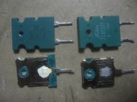
It gets worse - Toshiba, according to their website, do not make 2SA1302 and complementary... as far as i know, at least 8 years (probably longer). but you can still find them - except that they look a bit odd to anyone who has ever seen the genuine thing. Shops here are very uncritical as to what they order, and fakes are plentiful - some are downright ridiculous. Genuine 2SA1302 have a green plastic case, following the Japanese standard using green plastic for PNP or P-type parts, black for NPN or N-type. This was abandoned for cost savings in the mid to late 80s, which is, amongst other reasons, why Toshiba introduce the 2SA1943/2SC5200, which is essentially the same part with minor tweaks, but both types have a black plastic case.
Regarding the Toshiba 2N3773 - it is HIGHLY improbable Toshiba made them as a part of the regular lineup, but it is possible thay had a remarked version for someone else, that found it's way to the market. It is practically certain that you would not find one with the thick base, and flat cap - Toshiba TO3 never used such a case style, and besides, they have not made anything in TO3 for nearly 2 decades.
That being said, if there is such a thing, as one of the pics suggest, it should have the OLD Toshiba logo (the flowing script letters). It is most likely something like a remarked 2SD555 or similar (hopefully I got the number right...). It should be well over 20 years old, and the TO3 style case they used then invariably had a copper slug on the bottom (can be seen as a roughly mushroom shaped patch inside the circumference of the cap footprint, avoiding the base and emitter pins), and a slightly rounded top surface of the cap.
thank you ,bob, i see that you gave some more digging about the subject..
yes, the figures are quiete good...
i ll dig the thing to compare with the nippon products..
about the models, i ve got many for the same device...
i did took the ones that seems to be on par with the datasheet..
as modern bjts, 2SA1943/2SC5200 are fine. the simulator innacuracy is
not enough to explain the gap between those and onsemi s MJLs...
as noted by homemoder, i suspect the japanese to be secretives
fear that the others manufacturer would find the parameters that were enhanced by studying the models...
regards, wahab
Hi Wahab,
Thanks for the SPICE models. I looked at the datasheets for the 2SC5200 and 2SA1943 that you mention as being more modern examples of the Japanese power transistors.
With all due respect I have to say I am not impressed with either the datasheet or the devices. The datasheets do not even show ft as a function of collector current. These datasheets certainly counter the assertion that Japanese datasheets are better than OnSemi datasheets.
The data that is shown for these transistors is unremarkable in comparison with the OnSemi MJL3281. Beta linearity is about the same. Cob is specified as being 200 pF, which is less than the spec sheet number of 600 pF for the MJL.
BUT, DC SOA is only 400-500 mA at 100V, only about half that of the MJL. The MJL is at least as fast and has much more SOA.
Now, about that capacitance. The difference appears not to be as large as the datasheets suggest (remember, the OnSemi datasheet says 600 pF Cob for both the NPN and PNP devices, and we know that the PNP Cob is usually higher - that for the 2SA1943 is spec'd at 360 pF, typ.). I measured Cob for an MJL3281 at the usual 10V Vcb and got only 260 pF. At 40V it fell to 150 pF.
My conclusion is that the MJL is also better than this more modern Japanese part, and it has a much better datasheet to boot.
Cheers,
Bob
But is there *really* any difference? If the Moto/ON device has a higher spec'ed capacitance but measures the same or less... And is the real SOA of the Moto/On any better, or are the Japs sandbagging a bit more? Back in the old days, Toshiba used to put a *lot* of margin in their specs - the 2SD424 was only spec'ed at 1A at 70V, but would routinely pass the same 2.5A/100V torture test that RCA used on the butt-slow 2N6259. The same is probably true of the C5200. If it weren't, every QSC RMX1450 or 2450 that ever saw 4 ohms bridged would be coming back under warranty.
Hi Wahab,
The datasheets do not even show ft as a function of collector current.
The data that is shown for these transistors is unremarkable in comparison with the OnSemi MJL3281. Beta linearity is about the same. Cob is specified as being 200 pF, which is less than the spec sheet number of 600 pF for the MJL.
BUT, DC SOA is only 400-500 mA at 100V, only about half that of the MJL. The MJL is at least as fast and has much more SOA.
Now, about that capacitance. The difference appears not to be as large as the datasheets suggest (remember, the OnSemi datasheet says 600 pF Cob for both the NPN and PNP devices, and we know that the PNP Cob is usually higher - that for the 2SA1943 is spec'd at 360 pF, typ.). I measured Cob for an MJL3281 at the usual 10V Vcb and got only 260 pF. At 40V it fell to 150 pF.
My conclusion is that the MJL is also better than this more modern Japanese part, and it has a much better datasheet to boot.
Cheers,
Bob
thank you for the feedback, bob...
i know that you re an experimented ingeener, so i have some trouble
answering, as you re of good faith, and i cant but remember the times
when us designers and trademarks had trouble reaching the japanese
amps specifications , simply because their work was plagued by the
then motorola devices..just watch an audionics CC2, to see to what
extreme the designers were brought...in that amp, a triple paralele driver..
motorola of course...
meanwhile,, the japanese had to share their technology, as explained in this thread, allowing motorola/onsemi to reduce the gap badly...
now, on the technical facts you brought..
first, Ft as a function of current is not useful in the way it is measured
in datasheets, as it s at a FIXED frequency of 1mhz...
one who don t know the thing, would trust that if the Ft is, say
40 mhz at 4A, not only the device will have a beta of 40 at 1Mhz, but also
a gain of unity at 40 mhz..as you know, it s not true, as the MJL dont go over
6 mhz with a gain of unity and a current of 4A , and that s with a 2 R generator impedance , thus reducing to very little the influence of the capacitances..
on the same conditions, the 2SC5200 display 140 MHZ and although, it s
rather optimistic, it s more than an order of magnitude better..
these curves are good for narrow band RF amps designs, not audio design.
what we need as amp designers is also the curve of the bandwith of the device, constant currents and variable frequency, not only the contrary as in these datasheets, wherever they come from...and with realistic impedance source, of course....
reduced DC soa is imho a deliberate choice, as reduction of the silicon
surface reduce stored charges, making the device easier to switch off..
this also can explain why toshiba are way faster..
about the parasistic capacitance, you can expect toshiba devices
to display less values than the typical one displayed on the datasheet..
japanese have not the habit of overstimating their devices ratings...
regards,
wahab
I suspect we have a disagreement about the significance of ft and how it is measured.
BTW, the most important influence on ability to switch off a transistor in a linear application (achievable rate of change of collector current for a given base current being sucked out) is ft. This is why high ft is important in minimizing secondary (dynamic) crossover distortion.
Cheers,
Bob
i appreciate your patience ,bob, and we re in the process to be fully agree..
what you said is right , and i will add that it s not only the Ft, but
the ability of the device to sustain this Ft at the higher frequency
possible...
what i tried to explain you with my flawed english is that the Ft as
defined by datasheets, is in fact frequency dependent..
for a given current, the bjts have not the same Ft at 1 MHZ and at
5 MHZ....this is where the japanese parts are better than onsemi s :
they sustain their Ft in a wider frequency range....
regards,
wahb
IMO the best way to avoid this switch off problem is not to allow output devices to switch, to go in saturation (antisaturation circuits in stages before output),so ensure fast recovery (also using driver stage enabling this) . Than , performance diferences in SR, THD20, IMD etc. in whole real amplifier are negligible, but reliabilty with slower ONsemis is a way better...reduced DC soa is imho a deliberate choice, as reduction of the silicon
surface reduce stored charges, making the device easier to switch off..
this also can explain why toshiba are way faster..
Last edited:
IMO the best way to avoid this switch off problem is not to allow output devices to switch, to go in saturation (antisaturation circuits in stages before output),so ensure fast recovery (also using driver stage enabling this) . Than , performance diferences in SR, THD20, IMD etc. in whole real amplifier are negligible, but reliabilty with slower ONsemis is a way better...
What you saying here is that slower devices are are more reliable, this does not quite make sense. I use exclusively japanese power bjts because of cost and performance < 2sa1303, 2sa1186 and compl >and Ive never run into any reliability problems, there are thousands of high end amps dating from early 1980s using japanese devices and a lot of them are still in daily use, reliability is certainly not a factor, design is.
There is really no reason to appreciate possible local HF oscillations in output stages based on very fast power devices. They are even difficult to indicate.
I have no problems with oscilations, the faster device gives me better performance though, probably because happen to have very low cob . With very low cob transistors I find stabilty is much easier to achieve.
If stability was such a major problem no one would be using vertical mosfets either.
Reliability with slower Onsemi is better................., why not reliability with slower japanese devices, someone must be getting a lot of freebies and samples, pity one cannot get this from the japanese.
Last edited:
I have no problems with oscilations,
Good for you.
What I am trying to say is, that fT about 4-7 MHz is more than appropriate for very well performing amplifier for audio, no need to use output devices with fT 50Mhz.. . Problems with speed and linearity are very often in stages before output stage. How would You explain many amplifiers, using best output devices, but at the same time with poor linearity , with a lot of IMD products and stability problems wiht complex load? And mostly very expensive amplifiers, and often class A..What you saying here is that slower devices are are more reliable, this does not quite make sense. I use exclusively japanese power bjts because of cost and performance < 2sa1303, 2sa1186 and compl >and Ive never run into any reliability problems, there are thousands of high end amps dating from early 1980s using japanese devices and a lot of them are still in daily use, reliability is certainly not a factor, design is.
As You said, design is main problem (e.g. switch off problem..), not output devices with 5 or 50MHz fT .
And samples.. I had no one , all (several thousands) payed. Reliability means also You can use 2 pairs instead of 3 or 4 pairs, so in final lower costs and lower counts means better reliability (e. g possible thermal pad failure).
Last edited:
Reliability with slower Onsemi is better................., why not reliability with slower japanese devices, someone must be getting a lot of freebies and samples, pity one cannot get this from the japanese.
If you take proper SOA calculations into account, reliability should not be an issue. But, you might encounter a situation where a slower ONsemi will do the same total SOA with less output pairs, and now you have a trade-off between cost and squeezing out the maximum speed from the output stage - with equal reliability.
Granted, cost of the output pairs is not great compared to power supply and heatsinks, but it is right under those idems on the list - in particular when it comes to production in large quantity, as each transistor also entails costs for the mounting hardware and the mounting procedure itself, which, unlike 95% or more of the amp PCB cannot be done using automated pick and place machines. So, this is a real issue.
In the real world of home theater receivers and amps (which is the largest market for these transistors), it comes down to how much you can do with a single pair per channel. Moving to two pairs will often make the cost unacceptable as we are generally talking about at least 5 output channels. The transistors themselves won't ge the straw that breks the camel's back, rather the heatsink realestate needed to actualy fit those devicec (and you know they put the smalles heatsinks possible in there...). So, if you can claim 120W per channel instead of 100 with a single pair, you have an advantage. Of course, realistically all of these numbers are overestimated, but
a) it's a numbers game, 99.9% of the public has no concept of dB.
b) You can claim anything for THD as most customers would not be able to tell 10% from 0.001% THD, given the speakers this thing will drive.
c) the crappy transformer usually saves the outputs from blowing in real load situations, and who would want to actually test ONE channel at half power worst case in a 5 channel setup?
That being said, if it was not for the golden age of HiFi in the late 70s and up to late 80s (with a small resurrection in the 90s), the 'designers' of aforementioned home theater amps would not be able to design them.
The 2SA1302/2SC3281 are 25 year old designs. The 2SA1941/2SC5200 are essentially the same design with minor tweaks. ONsemi and NSC versions are all derivatives with tweaks. You could go 25 years back in time and design most of tosays cutting edge designs with transistors that were available then, with the added bonus of having lots of JFETs to play with as well.
Similairly, the Sanken camp had 2SA1170/2SC2774, from which 2SA1216/2SC2922 were developed, followed by 2SA1295/2SC3264. All derivatives with very close specs. So much for 'more modern transistors'.
On the other hand, a closer look at what Sanken has been doing reveals much the same strategy as ONsemi, but coming to it 'backwards'. Later derivatives of the original LAPTs feature slower speed but higher SOA. Also, Sanken has a slower, cheaper 3-diffused lineup and faster, more expensive LAPT lineup (also a darlington lineup based on the 3-diffused parts).
IMO the best way to avoid this switch off problem is not to allow output devices to switch, to go in saturation (antisaturation circuits in stages before output),so ensure fast recovery (also using driver stage enabling this) . Than , performance diferences in SR, THD20, IMD etc. in whole real amplifier are negligible, but reliabilty with slower ONsemis is a way better...
I think you misunderstand, based on the semantics of "switch off". Let's forget the word switch for a moment. In a linear application like a power amplifier output stage, the power transistors must be able to change their operating current quickly when HF signals at high amplitudes are being passed, like 20 kHz into 4 ohms. A high voltage slew rate produces a high current slew rate.
In the usual EF output stage driver, the driver can supply a lot of current to increase the current quickly in the output transistor (i.e., turn it on). However, the driver can only suck out an amount of base current from the output transistor usually equal to the driver's bias current. This limits the rate at which the transistor can be turned off (i.e., reduce its collector current). This has nothing to do with hard on-off switching or saturation. This has everything to do with pulling minoity carrier charge out of the base. For a given operating current, the amount of minority carrier charge we have to pull out is inversly proportional to ft.
It can be shown that the achievable current rate of change with a power transistor is proportional to the base current times the ft of the device. Look at the hybrid pi capacitance and the gm of the device and you will see this relationship. Recognize that both hybrid pi capacitance (at meium collector current and above) and gm are proportional to collector current.
Cheers,
Bob
- Home
- Amplifiers
- Solid State
- bipolar (BJT) transistor families for audio power output stages