The amplifier will be all nigth long playing into a 7 ohms resistive load
...well, a little bit inductive too, and having 2.2uF capacitor in parallel with the resistance.
50 watts average will be pumping all nigth long, an endurance test, the amplifier is protected using fuses and a fan will be blowing all nigth long, this nigth will be hot, temperature now is 30 degrees centigrades.
regards,
Carlos
Attachments
Last edited:
This is the best recording i could made.
YouTube - Dx Blame ES, better recording
The multiple encoding steps used killed the quality, the encoding to MP3 (wavepad software, a freeware), the encoding using the slide movie program, the Photo2Video software and the final encoding, and AVI codified to the youtube system.
But resulted reasonable and it is good to demonstrate the power amplifier quality.
Thanks to Doctor Self for the treble and thanks to myself for the bass.
regards,
Carlos
I see that some of you feel shocked with a so big Cdom, in special
using two, the normally used in my amplifiers are 22pf to 27pf, so, i am the first to stand against that kind of use, i also think this is a huge exageration.
I agree this is too big, but a need fellows, when i have tried to reduce, i found oscilation using 68pf, 56pf, 47pf, 39pf and 33pf.
I have tried combinations, using only one...but have not worked, the heatsink turn hot, the iddle power consumption climbed to danger levels.
I have an enormous responsability with the ones build my amplifiers, all them reliable, i cannot put them under a risky sittuation.
So, i am keeping the huge capacitors there, double Cdom, one to each transistor as this Doctor Self Vas uses dual transistors (identical to the book)...different was the Cdom, as Doctor Self suggested 100pf from the second transistor colector to the first transistor base, and so it is.
The one assemble, has the freedom to tweak his own amplifier, he can even remove the stabilizing capacitor, maybe his board will be less sensitive to oscilations too.... and the one can try several options.
My obligation is to offer to forum folks a guaranteed schematic, reason why it is pumping power those last two days, and today will be endurance using 3.5 ohms load together 2.2uf in paralell.
Surviving, will receive my guarantee tag.
There are already 4 brazilians assembling.
Please, listen the youtube Dx Blame ES, microphone recording, wich link is bellow, follow the adress bellow the signature please.
regards,
Carlos
More Blame EX recording, samba for my local friends
and for the forum Brazilian members too.
YouTube - Audio amplifier, Dx Blame ES plays samba
Increase the volume, all them, the tripple encoding "eats" volume.
regards,
Carlos
and for the forum Brazilian members too.
YouTube - Audio amplifier, Dx Blame ES plays samba
Increase the volume, all them, the tripple encoding "eats" volume.
regards,
Carlos
Member
Joined 2009
Paid Member
The amplifier died during the endurance test..DO NOT BUILD for a while
The amplifier have not survived the 3.5 ohms plus 2.2uf endurance test, while was operating into my speaker, not reaching the distortion level, using speaker loading plus resistance, plus capacitor, behaved fine...but doing the tests to Pavel, i have overdrive the unit with square wave, 10 khz and them plaft ploft pow!.... the amplifier gone.
Before this moment i was inspecting the waveform, was perfect, but when i have increased the generator level to see what gonna happens forcing the limits, the amplifier started to oscilate and gone.
I have fixed and gone once again, them my solder finished and also my good will.
The amplifier has not passed the endurance into 3.5 ohms plus 2.2uf, BURNED!, this means to me it is not stable enougth, because my other models survived this same test using computer generator without troubles.
DO NOT ASSEMBLE till i return, next year, after Christmas and a very Happy New year to everybody.
Will buy more solder and gonna change something and try once again, but, in advance this amplifier will Blame Dx in the place to be Blame ES..and i can put some money on it that it gonna receive a sledge hammer hit very soon.
Lovely sound, but if cannot be overdriven..no way!...the supply fell down to 33 volts, so no problems about transistors..some unstability that i do not know where or why.
Regards,
Carlos
Attachments
Carlos,
just curious - could you kindly show an oscilloscope measurement of 10kHz square response into 8ohm//100nF load?
Thanks,
Carlos -
very sorry to hear that. But please mention I asked only for 100nF, not 2.2uF. 2.2uF and 3.3uF I ask only for my designs
")
Regards,
Carlos -
very sorry to hear that. But please mention I asked only for 100nF, not 2.2uF. 2.2uF and 3.3uF I ask only for my designs
Regards,
it s not the cap that did kill it, as thanks to the RL output filter, it was
stable under such a capacitive load,...the thing is that when coming from a clipping with a square wave, the power device that is supposed to be switched off had to first resist a spike of current in excess of 20 A with a full rail voltage...with a 10KHZ signal, it s deadly...
i made the simulations of his amp yesterday..
What have you found into the simulations Wahab
The amplifier cannot work full power with square waves and high frequencies, explain this please, in details?
It was playing the same peak to peak voltage i had with sinus, them i have switched to square, the same level...but i imagine what you mean, the current was constant into the maximum level for a very long time...i see..... cannot work this way... also transient because switching on and off.
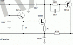
That Cdom was really from base to colector, so, nothing very strange with that, only the value seems too big for you and also for me.... i had to use, without it oscilated as a crazy donkey.
First transistor had the coletor to ground, so, if you install a capacitor from base to ground you are, in the reality, installing a capacitor from base to colector.
Your ideas will be applied, as i will try once again next year, the "passed away" amplifier sounded very good, will give it a new chance.
regards,
Carlos
The amplifier cannot work full power with square waves and high frequencies, explain this please, in details?
It was playing the same peak to peak voltage i had with sinus, them i have switched to square, the same level...but i imagine what you mean, the current was constant into the maximum level for a very long time...i see..... cannot work this way... also transient because switching on and off.
That Cdom was really from base to colector, so, nothing very strange with that, only the value seems too big for you and also for me.... i had to use, without it oscilated as a crazy donkey.
First transistor had the coletor to ground, so, if you install a capacitor from base to ground you are, in the reality, installing a capacitor from base to colector.
Your ideas will be applied, as i will try once again next year, the "passed away" amplifier sounded very good, will give it a new chance.
regards,
Carlos
Attachments
Last edited:
The amplifier cannot work full power with square waves and high frequencies, explain this please, in details?
It was playing the same peak to peak voltage i had with sinus, them i have switched to square, the same level...but i imagine what you mean, the current was constant into the maximum level for a very long time...i see..... cannot work this way... also transient because switching on and off.
That Cdom was really from base to colector, so, nothing very strange with that, only the value seems too big for you and also for me.... i had to use, without it oscilated as a crazy donkey.
First transistor had the coletor to ground, so, if you install a capacitor from base to ground you are, in the reality, installing a capacitor from base to colector.
Your ideas will be applied, as i will try once again next year, the "passed away" amplifier sounded very good, will give it a new chance.
regards,
Carlos
hi, carlos,
i made simulations, but i didn t tweak the design...
the distorsion was very low, in the vicinity of 0.002 at 1KHZ...
such low thd is obtained because you designed a monster in matter
of open loop gain, at 120 dB +, more than one million, but at the same time,
the roll off of the gain is so abrupt that it s less than 60 dB at 20KHZ...
anyway, this make the amp highly instable, and without the self and resistor
at the output, it would have been instable even with a 100nF caps with the load...i didn t check how to improve the thing, as the design seemed to
work in your lab...
i will make some tries to see what has gone wrong in this amp, since i ve got the file in my simulators, it will not take a lot of time...
regards,
wahab
The amplifier cannot work full power with square waves and high frequencies, explain this please, in details?
First transistor had the coletor to ground, so, if you install a capacitor from base to ground you are, in the reality, installing a capacitor from base to colector.
Carlos
there s a problem with square waves, as when the amp go from a rail
to another, there s a crossconduction which exceed 20A during a short
time, but at 10KHZ, this is much too repetitive, so surely one of the output device will blow first, saving perhaps the other..
the capacitor must be seen as connected from a collector of the
differential to ground, thus slowing the input stage, as explained in
a post earlyer by BV, it seems..
this slow down not only reduce the bandwith, wich was wanted,
but also reduce the ability of the differential to control rapidly the vas..
i can t elaborate more, as i need to study the thing a little more..
regards,
wahab
The amplifier have not survived the 3.5 ohms plus 2.2uf endurance test, while was operating into my speaker, not reaching the distortion level, using speaker loading plus resistance, plus capacitor, behaved fine...but doing the tests to Pavel, i have overdrive the unit with square wave, 10 khz and them plaft ploft pow!.... the amplifier gone.
Die Soft?
Time to add some protection circuitry!... i have overdrive the unit with square wave, 10 khz and them plaft ploft pow!.... the amplifier gone.
Perhaps you think that will spoil the sound, but I think you will find it improves the smell.
burning, it goes in flames, yellow flames, when other pops a blue ligth and the transistor case is opened with a clear hole or a slice is busted!
Also the unit burns the stop resistors...i do not know if those resistances are too much weak (new ones i have received from Greece) but they carbonize easy and smells a lot.
Member
Joined 2009
Paid Member
I have decided to put it on ice, gave me a lot of troubles and it is really,
not that reliable the way i want to my amplifiers, will not kill the one till Todd (taj) say OK! to that, because that helped me a lot, he even made schematic and was producing (starting) boards.
Well, i have noticed the HRII is almost the same, and worked stable in my home (4 units made) and also stable with my Orkut friends (more than 12 have build in Brazil, also Nordic has distributed 100 boards, or 50 stereos wide world and people said they loved the sonics....so....as HRII had not a dedicated thread i will ressurrect the HRII amplifier and will post the schematics and so on.
The HRII has a board layout ready, schematic ready and a lot of interesting informations into the Greg home pages...a winner.. the one have not oscilated, and the main difference is the CCS to the differential long tail, observe the HRII has not the ccs.... i have some suspections about it, because it is the main difference... the amplifiers are almost the same,.
Having the Taj Ok!, the permission or agreement to put the Dx Blame ES on ice, then i will open a thread called "revisiting the HRII".... after i will check if revisiting exists in the english language..i am not sure...maybe ressurrect or something alike.
I am interested into your ideas about Wahab, despite i will change my direction, the reason why the amplifier was unstable is something that is killing me of curiosity.
regards,
Carlos
Attachments
carlos;
i have some remarks about your test conditions : it s genuine
torture....your 7R load is unductive and amps don t like that..
add the 2.2 uF capacitor and the RL output circuit, and that make
an explosive mix, literaly...anyway, it seems that your earlier amps
did survive this mistreatment...
i send you two schematics, the modified one as ES2 and the original
as ES1, for comparison purposes..
in the moded shematic, you can see components that are not connected,
as the amp doesn t ned them, they are here only if the cautions i took
are not enough and are here mainly for explanation of their eventual role.
now let s look at the original schematic :
the CCS is moded to reduce the tail current, as proned by BV...
also, it s simplified as it was the plan that was used in
douglas self schematic, and it was badly flawed in fact..
reduction of current reduce the transconductance in an
aim for stability without increasing the degeneration resistors..
the RC circuit from inverting input to non inverting input must be
suppressed, as the end that is connected to the non inverting input
is in fact closed to the signal source , thus making the amp response
amplifying more at very high frequency, creating instabilities..
as you can see , the eventual place of this RC is between the two
collectors of the differential, but in principle it s not needed..
it can replace the 100 pf shunt capacitor, but as you can see,
this latter was also suppressed..
the offset problem you experimented has his source in the
VAS buffer resistance between emitter and negative rail..
1K is not enough, as the buffer will see only 940 uA curent,
thus, the current pumped by the following transistor is too
high in comparison, shifting the dc balance, and making
the amp try to adjust this bias, thus creating DC offsets..
with the new value, no need of different resistances for the
legs of the current mirrors.
beside, a reduced resistance allow better switching of the vas..
also, the two base of the differentials have now the same 12K
resistance...the measured offset at the output is now 60uV,
on par with the high loop gain at dc..
Cdom is increased to 68pf...here, it is a matter of real world
adjustement...
also, this cap see the full rail volatages, and must be of quality,
preferably a stiroflex..if you use ceramic caps, it s perhaps better
to use a 150 pf in serial with a 120 pf, as they will sustain
more voltage while being still linear....
the Vbe multiplier use a better transistor, as it s important
to use a fast one...
also, the cap that shunt it is suppressed, as it can generate
oscillations...this caps is neutral only if the VAS collector current
is perfectly constant..in the original blameless, a current source
was used to load the vas, not a bootstrap...
i did not connect it, as it s your role to experiment with it, although
i can only warn you that it s a sensitive issue...
the output RL filter is suppressed..in principle, the amp is
stable under any capacitive load without it..
nowadays, i did draw it, if ever it s needed..
high values of L and R are only the prove that the amp
is not naturally stable, so rather than increasing these values, it s better
to tackle the origin of the problem..
here we are..i surely did miss some things in my explanations,
so if i did forghet something, just tell me about it, i ll come back
with the numbers...
regards,
wahab
Attachments
I see you are more prepared than i am to manage this project
I would like to invite you to accept, alike a gift or inheritance, this amplifier, to you... to go on with this one, to develop this amplifier, to assemble and to test real world to offer forum folks a nice sound amplifier... i would like you to accept, to produce the needed testing, having Pavel help (he is also excelent)...this gonna be a great benefit to the people of this forum.
You see, i do not even know what happened!.... i am alike a blind man in the middle of a gun shot, you seem has more knowledge, and together Pavel, that very fast perceived the time bomb (and really exploded!) he knew fast the the amplifier was, let's say, problematic.
I have other design, almost the same, the HRII, more stable that i want to ressuscitate, to explore it a little bit more.
This one has CCS, and may have CCS to the VAS too, and i was never happy with ccs..we... ccs and me, have not a nice conversation...be confortable to produce the changes you perceive as good, but accept the charge to manage the thread and to make it good to forum guys.
I am giving up, going to the HRII, as i told you, this one can he a very nice thing to our forum, sounds absolutelly great!
The HRII has not all that treble, but is very stable and i do not want to develop this one because i do not feel myself prepared, or skilled, or having enougth know how to do that.
You are receiving a formal and official invitation to accept the charge and to take care of this thread.
Do this for us, be helpfull and cooperative, spend some time with us...make your name registered as someone that have cooperated and have know how to do that.... and, accepting this thread management, you gonna prove that.
Pavel Macura is alike a filter... a fine grain filter...when things seems not very good he use to come, i do not love him deeply because of that, but i really think he is very helpfull to check designs.
regards,
Carlos
Last edited:
carlos,
as can be easily seen, there was only minor tweaks...
don t be deluded by this experience, as we have all
experimented scores of bizarre amps that were not working
as they were supposed to do...
my trash bin is full of aborted projects...
often, it was only a few components that were miscalculated,
and yet, it was enough to make the thing despicable..
thanks to the forumers here present, i do learn a lot
every day, and it happens that one person give me the
answer to a problem i was unable to tame down for a long time...
anyway, as proved by your experimentation, the design work,
the only mistake you did was to directly mistreat the thing badly..
this amp need a very few modification, that were in fact reaveled
well earlier in the thread by the diyers...
i can only advice you to listen to others, so you wont be coined
to learn the things the hard way...
well, we are all in the same boat, and while we discuss about this
project, other forumers are badly suffering making their projects
work the right way..we are no exception in this matter..
anyway, i think that we can collectively make this amp work, with
great perfs...
pavel s expertise is of course of great value, and i don t doubt
that he will take a look at our tries and give valuable councels,
as he has a lot under the hand...
for the time, carlos, don t bother, and take some good times in this
year end, so next year, you ll be ready to bring again your enthusiasm
that is greatly appreciated in theses forums...hey! it s cold here in europe,
last week it was as low as -12° C....you are under the sun, enjoying cools
days, walking along the beaches...you just don t know how lucky you are...
regards,
wahab
My technicall resources are exausted related this amplifier
and i feel the better idea is to let someone more skilled to conduct the thread.
My other resources, time, solder and parts are also going to the end, transistors i have not too much anymore, only a couple of pairs, and this amplifier have "eated" a lot of them, maybe 3 BD139/140 pairs , 1 MJE340/350 pair and three power unts...it is time to give up and to manage another amplifier, and the one elected is the one i have already test hardly, also forum people has assembled, the lovely, reliable, non explosive, HRII.
Well, the thread is Orphan, maybe Pavel accept the invitation to go on with this thread, or Ostripper that loves such amplifiers, also Bigun, also MJL21193 or some other skilled, proved, experienced accept the charge... better if old, responsable, respectable by forum people, and if famous will be a good idea too, as people will run to ready his threads.
Conduct a thread is not easy, it is hard and not something to young guys searching for easy fame or weekend adventure, ask for our time, dedication and a lot of hard work, we have to give follow up, ask all questions, help people to build, produce boards, test boards, produce schematic and check the schematic in real life built amplifiers... and also, to stay in front of the computer for many hours long..healthy people is needed to do that.
The thread and the amplifier will be on the ice till someone respectable take to itself the responsability.
I will criticise, if someone not good enougth to do that come to manage the thread, as i told, must be respectable old folk, more than 30, or young genius, that has 40 years experience having 20 years old (ahahahahah!)
I gave my contribution on this amplifier, and i decide that is enougth, the time spend, the parts burned and the need of solder (ahahahahah!) drive me to do this way.... gladly i declare!
Thread is Orphan!
_ Doctors Pavel, Chocoholic, Ostripper, Bigun, MJL21193 invited.
Anyone?
I will go to the beach to have some good walk and watch the girls passing by.
Carlos
Last edited:
- Status
- This old topic is closed. If you want to reopen this topic, contact a moderator using the "Report Post" button.
- Home
- Amplifiers
- Solid State
- Dx Blame ES .... based into the Blameless, i am trying a new amplifier