Or, a quick lesson in don’ts.
This amp was built by a company with a good reputation, and was part of their introductory line of amps released in Aug 1990. Price was likely around $550. Their 50W x 2 was $350, and 125W x 4 (just two of this model in one case) was $926.
As amc32 already pointed out in this post, I’ll reinstate:
- don’t mount your vibrating automotive PCB’s through your BCE’s.
While tracing the circuit to make the schematic, I had a couple of “do WHAT?” moments.
Anyone else bored enough to nitpick this one?
Attachments


Well, that's typical. Maybe I mislead by representing the jumpers in the schematic as R's.
But those little 0 ohm jumpers must pass the entire primary winding current, which is probably 99% of the current drawn by this amp at full output. According to the manual, that's 45A !!!
!!!
Apparently that was a compromise for the long skinny PCB shape.
>>Lesson 2 – don’t get so stuck on a PCB geometry that you make major compromises to high current or sensitive traces in your PCB layout.
But those little 0 ohm jumpers must pass the entire primary winding current, which is probably 99% of the current drawn by this amp at full output. According to the manual, that's 45A
!!!Apparently that was a compromise for the long skinny PCB shape.
>>Lesson 2 – don’t get so stuck on a PCB geometry that you make major compromises to high current or sensitive traces in your PCB layout.
Attachments

-don't hang the transformer in mid-air... from the pcb's which are hanging from the switching transistors
-don't parallel tip35's or 36's with no emitter resistors (already stated)
-don't use long slim caps and not at least glue them securely
Can't see the schematic for some reasons
-don't parallel tip35's or 36's with no emitter resistors (already stated)
-don't use long slim caps and not at least glue them securely
Can't see the schematic for some reasons
Can't see the schematic for some reasons
To get a readable full size image (IE), I have to click the "expand" button on the bottom left of the schematic -after it has already expanded from thumbnail size. Same with the specs page. Original file size was about 800k, but it looked good resized to 200k on this end. I can post it as a link if need be.
Or is it not showing up at all?
It's about as simple as a supply gets and may be helpful for someone looking into how things work.
Last edited:
Class AB amplifier designers trying to do SMPS and car audio. The result looks like a joke, particularly the toroid hanging and the twisted magnet wires.
btw: There was a better way to do a SMPS with TIP35 and TIP36 and the parts available by that time, it was just a matter of copying the proportional drive topology from the old PC power supplies (still good enough to be in use today).
btw: There was a better way to do a SMPS with TIP35 and TIP36 and the parts available by that time, it was just a matter of copying the proportional drive topology from the old PC power supplies (still good enough to be in use today).
Proportional drive uses a current transformer to sense collector current, and applies the output to the bases, so instantaneous base current is always proportional to collector current for best switching efficiency and lowest losses when the amplifier is idle. The optimum proportion is typically 1:5 (1:5:5 or 2:10:10 turns). This also allows to get the lowest losses at high collector currents.
The circuit uses some gadgets (with resistors, capacitors and diodes) to provide a negative base current spike at the end of the cycle for quick charge removal and fast turn off, and provides negative bias for the bases of the transistors that are off, something that allows to use them close to their ratings safely.
A TL494 (available since early 1980s) usually assists the circuit to keep switching frequency stable, and to provide duty cycle control and regulation if desired, although it can be made self oscillating (no active components) by using a saturable core for the current transformer (a kind of ferrite whose saturation is very abrupt and predictable). So yes, regulated efficient SMPS in car amps were already possible by that time.
This topology is good enough to be used today in most low cost electronic halogen lamp transformers and fluorescent ballasts. I tried it in a 230V to 14V 125A adjustable power supply prototype a few years ago and I managed to get nearly 1800W reliably with just four MJE13009 TO-220 bipolar transistors on the primary side and efficiency comparable to current MOSFET technology. The design of the current transformer is critical, though, coupling has to be very good, leakage inductance degrades switching speed a lot.
Last edited:
I tried it in a 230V to 14V 125A adjustable power supply prototype a few years ago and I managed to get nearly 1800W reliably with just four MJE13009 TO-220 bipolar transistors on the primary side and efficiency comparable to current MOSFET technology.
Very impressive.
And thanks for the explanation!
Last edited:
Just for your interest: I've sent my MM250 (most probably the next generation of M&M amps) to somebody who benchmarked it for me.
This one has a better concept all over...
It's a Mantz!
And here's the link:
M&M Electronics MM250
It's an interesting site at all and if anybody needs german words to be translated, just ask!
This one has a better concept all over...
It's a Mantz!
And here's the link:
M&M Electronics MM250
It's an interesting site at all and if anybody needs german words to be translated, just ask!
Yeah, me too. I was cynical as soon as I opened it up.
-This supply dosen't work in push-pull mode, the bases of all 8 switching transistors are connected to a single TO220 driver. So it should have a turns ratio of around 7:1 to get 125W/ch. It looks kinda sparse for that. I would also expect heavier gauge on the input with that kind of step-up, but all turns appear to be the same...
Other than one picture of a 4ch in the "What's New" section of CA&E, I've never seen another one of these.
This particular amp never made it out of the shop. It was installed (when new, purchsed from a distributer in ATL) and ran for about 5 minutes before beginning to distort a little and shutting off. The shop owner opened it up and found the 12V battery lead was disconnected... Resoldered, and it never powered up again. He packed it up to return for repair and never shipped it.
19 years later, he's cleaning up shop and found it still boxed up. I happen by and he hands it to me, "Here, this should to be a really nice amp. There can't be much wrong with it, and it's supposed to be 250W" and told me what had happened with it.
What I find interesting is the heatsink is stamped "Burned in 8 hrs." Sounds like it Burned in 5 minutes instead.
Just speculation, but chances are the rest of these suffered a simliar fate and were returned, thus their rarity.
gisewhcs:
Obviously your model is what replaced this ill-fated one. Do you have a date on it?
I'm torn as what to do with it. Get it operational and sell it to someone with an affinity for M&M as a collector piece, keep it for posterity, or redo the power supply with pwm control and enjoy it?
I also believe it's the direct succesor of yours, it even nearly has the same heatsinkdesign and color!
I just looked for any dates on my amp, but didn't see one...
But I would guess it was produced >1991, because it already has the barcode on the typical ZED-serial/model-sticker on the bottomplate.
My older Crunch amps don't have the barcode yet and one of them is dated 8-8-1991.
But i will open the newer Crunch revisions (already with the barcode), and have a look for dates!
Perhaps this will narrow the time slot!
Is it really from the same brand? The power supply even seems to be regulated, the improvement in design is huge.
The power supply of the first amplifier in fact is push-pull self-oscillating (it flips polarity when the transformer saturates), but base current is not controlled in an optimum way, it just has some dependency on Vce-sat. Also, I think the 10u capacitor on the other side of the base windings is shown with wrong polarity.
The power supply of the first amplifier in fact is push-pull self-oscillating (it flips polarity when the transformer saturates), but base current is not controlled in an optimum way, it just has some dependency on Vce-sat. Also, I think the 10u capacitor on the other side of the base windings is shown with wrong polarity.
Is it really from the same brand? The power supply even seems to be regulated, the improvement in design is huge.
The power supply of the first amplifier in fact is push-pull self-oscillating (it flips polarity when the transformer saturates), but base current is not controlled in an optimum way, it just has some dependency on Vce-sat. Also, I think the 10u capacitor on the other side of the base windings is shown with wrong polarity.
It appears they just farmed out production to Zed after this model, so no similarities to be expected. Forget the learning curve, just farm it out...
The 10u is indeed drawn reverse polarity, as is the Vcc- filter cap, and all 8switching transistors are TIP35's, not a mix of 34/35. Sorry about that. I'll relabel an post corrections if anyone cares.
Hmmm, I'll have to stare at the self-oscillation a bit to get that. The polarity of that 10u should have caught my attention, but I just kept expecting to find the two banks of TIP 35's switching separately. In fact, that's why I bothered to draw it out.
Again, thanks for the clarification Eva.
Yes, it's the same brand, but not the same producer/designer.
My MM250 was built by ZED-Audio, I don't know who produced the PA-250.
Here's a scan of the CA&E article from July '90. The heatsink and overall look is very similar to your Zed amp.
The manual says "Designed and Manufactured in California U.S.A.", and
"PDM is a registered trademark of Anderson Miller Co."
"PDM Power Supply" is listed as a feature.
Attachments

Last edited:
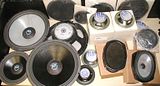
DON't tear that one up Tim... I want that M&M ... Real bad... Would go with my M&M speaker collection nicely. Let me know if you will let it go. As many times as we have chatted back and forth Tim, you never mentioned you had any M&M. Guess I didn't ask either.

Last edited:
Hey Tom, long time no hear! I do hope all is well over there. Got that tractor running yet?
This is the only M&M I have, and the only M&M amp I've seen except for the picture of gisewhcs' MM250.
I wouldn't dare tear it up. A power supply redo would be from scratch, on a new board, and plug right into to the existing molex plugs. The same BCE mounting would most likely be the only option to avoid drilling. But unsoldering the power supply leads and cutting a couple of wire ties would be inevitable, and so far I couldn't bring myself to do even that.
Have you seen this one before?
- Status
- This old topic is closed. If you want to reopen this topic, contact a moderator using the "Report Post" button.
- Home
- General Interest
- Car Audio
- M&M PA-250 amplifier investigated