Studies, are not everything. Success it.
I have not seen any evidence that special RF ingress protection is or ever was the key toward a successful audio product. To me, such special protections are just another attempt "to make a difference" on a market where differentiating from your competitor is a critical factor. Otherwise said, just another sales pitch, good for the Stereophile readers.
Do you have such evidence?
Last edited:
I am concerned, within reason. I don't think potential RF ingress issues require any special or outstanding measures. To my experience, common sense practices like good grounding, proper shielding, smart wiring (reducing loops), filtering, decoupling, ground loops (or lack, thereof), RF input filters, etc... are addressing 99.99% of the potential issues. No need to get paranoic about, and shielding audio gear like a RF transmitter, designing power supplies for tenths of MHz rejection, etc... is a waste of time, energy and money. Of course, there are always pathological cases like people living in the proximity of RF transmitters, but I don't think they should set a design target.
For example, while I absolutely agree that toroidal transformers are allowing some (?) RF ingress through the winding capacitive coupling, I have never seen any shred of evidence or credible study about the impact (and superiority, thereof) of (e.g.) R-core or even split bobbin transformers on the audio performance. Moreover, if such impact exists, the transformer is not necessary the evil part. To me, (e.g.) building a gain stage with virtually zero PSRR, then complaining about the transformer/power supply allowing RF ingress, is plain wrong design.
I appreciate your response.
Here's something John might like. A quote from someone's presentation:
"The AudioFool Viewpoint
• The Myth: “We can hear stuff above 20 kHz”
• Reality: Some distortion mechanisms DO
produce audible artifacts from ultrasonic
signals, but we hear the problems, not the
signals!
• Intermodulation distortion (40 kHz – 30
kHz = 10 kHz)
• Slew rate limiting within electronics of
ultrasonic output of a mic (or of square
waves from a test generator)"
The rest can be found here
http://audiosystemsgroup.com/Ferrites-Ham.pdf
It all sounds quite reasonable to a noob like me. What do you guys think?
OK, by the same fellow, named Jim Brown, who gave a presentation at the 2008 Fall Convention of the Audio Engineering Society in San Francisco.
http://audiosystemsgroup.com/AES-RFI-SF08.pdf
Seems like a worthwhile presentation to have attended.
http://audiosystemsgroup.com/AES-RFI-SF08.pdf
Seems like a worthwhile presentation to have attended.
Attachments
Hi Kannan,
If you read syn08's post, copied here:
The susceptibility of the circuits that comprise the equipment will determine how much injected noise is acceptable.
Never assume anything.
Look at any good piece of test equipment for clues. What you will see is generally far more attention paid to shielding and power supplies. If you then have a peek at some consumer audio equipment, you should be able to see clearly what the differences are.
Last point. Noise reduction from interference is a money game also. How far do you go? How much money is spent on the pretty box? How far down your noise floor is depends on how much money and research goes into the design (= money). Everything is a trade-off.
-Chris
No one can give you any numbers for this off the cuff. There are so many variables that have an effect. The one thing that is true though, many (as in most) consumer electronics are built with very substandard power supplies. So the current state of the art in audio is very poor and very basic. Why else would a PS Audio power line conditioner (actually a power re-generator) actually make any difference to a product plugged into it?now we have no answers to this - what frequency max and what amplitude of this range can cause problems in a line amplifier?
If you read syn08's post, copied here:
He has pointed out the basic issues. I agree completely here. Just take basic precautions and use common sense. Too often, I believe that a power supply is just "tacked on" without too much thought. Same goes for thermal issues.I don't think potential RF ingress issues require any special or outstanding measures. To my experience, common sense practices like good grounding, proper shielding, smart wiring (reducing loops), filtering, decoupling, ground loops (or lack, thereof), RF input filters, etc... are addressing 99.99% of the potential issues.
The susceptibility of the circuits that comprise the equipment will determine how much injected noise is acceptable.
Not alone. Never forget the other cables running through the wall. Even a display may allow enough noise to enter to cause problems. That enclosure will attenuate the offending signals some, but we're back to my last statement above this quote.Can we assume that 3 mm Aluminium enclosure would adequately shield a line amplifier from radiating RFI?
Never assume anything.
Again, there is no easy answer for this. John could probably answer for circuits he designed and built (the build is another very important factor here). The way I approach this, and probably many others, is to follow good design practices and layout guidelines. Once you have those down, you just build that way. If you need more shielding because your noise is too high, then you need to investigate and find out why. Also, Aluminum will not block electromagnetic disturbances. So your wiring could easily couple to a noise source. May the games begin.I also assume that PS line should get to the rule so defined for RF noise( If John can give us some guidelines on Freq/amplitude guidelines for PSU noise - will be nice?)
Look at any good piece of test equipment for clues. What you will see is generally far more attention paid to shielding and power supplies. If you then have a peek at some consumer audio equipment, you should be able to see clearly what the differences are.
Last point. Noise reduction from interference is a money game also. How far do you go? How much money is spent on the pretty box? How far down your noise floor is depends on how much money and research goes into the design (= money). Everything is a trade-off.
-Chris
Hi ikoflexer,
Jim Brown is a smart cookie. His stuff is well worth reading and he has a wealth of information on his site.
I'd recommend you start reading. Remember to keep a perspective on what effects they are talking about. His concepts are solid and based in reality from what I can recall.
-Chris
Jim Brown is a smart cookie. His stuff is well worth reading and he has a wealth of information on his site.
I'd recommend you start reading. Remember to keep a perspective on what effects they are talking about. His concepts are solid and based in reality from what I can recall.
-Chris
To minimize confusion here, I have found virtually everything is important in serious audio design. RF contamination is just one thing.
I would like to point out that of the 3 stages: We are now at stage 2.
This is: 'It exists, but it is not important'
IF you want to read anything further on AC line contamination, I recommend getting and reading the IBM article from the IEEE from Ikoflexer. Thanks Ike!
I would like to point out that of the 3 stages: We are now at stage 2.
This is: 'It exists, but it is not important'
IF you want to read anything further on AC line contamination, I recommend getting and reading the IBM article from the IEEE from Ikoflexer. Thanks Ike!
OK, by the same fellow, named Jim Brown, who gave a presentation at the 2008 Fall Convention of the Audio Engineering Society in San Francisco.
http://audiosystemsgroup.com/AES-RFI-SF08.pdf
Seems like a worthwhile presentation to have attended.
I did attend. While it was worthwhile as a refresher on these issues, I don't think there was anything new presented.
jd
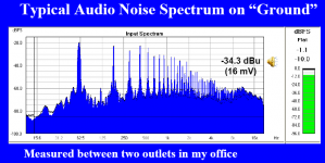
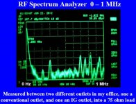
Yesterday I forgot to show the measurement extended to 1GHz. We can see FM broadcast, TV broadcast and GSM in the PSU output spectrum. Of course, the very high frequencies are coupled from the air.
I can see from your measurement that GSM, TV broadcast, FM broadcast, etc... do exist.
And what about the spectra from 10-20GHz? There are Ku band satellite DTH TV broadcasts there, high power transponders with 27 MHz bandwidth, carrying digital signals. Those are much powerful than the next GSM tower! Not to mention the evil Ka band at some 54GHz.
So? Should we get tin foil helmets? Should we encase our amps in Faraday cages?
Come now everyone. The amount of RFI that one might have at the output of ones power supplies and its effect of sonic accuracy of an audio system, is location and component dependent. If SYN08 would just read the IBM paper that we have put forth, then we would have something to work with, at least. After all, the researchers at IBM found that electric stoves do a lot of power line pollution, and that is just one example.
IF you have ever had obviously audible problems with RFI, usually it is related to detection of existing RF transmission that can be very high, indeed, IF you live line of sight to a broadcast tower, for example. Usually we like to design, reasonable worst case, especially the Blowtorch (remember the Blowtorch preamp)? Serious attention to RF rejection is included in that design, perhaps not as much as PMA would do, in his preamp design, but perhaps more than some more inexpensive preamps, where every penny counts.
Equally significant to RF transmission, RF generation in the home and on the local power line, is the generation of RFI from audio switching power supplies and DIGITAL playback systems such as CD, DVD, and SACD. Any residual digital processing is also transparent to typical IC regulators, so this is important, as well. This is why the CTC Blowtorch used separate bobbin power transformers, a series common mode choke, 3 series regulators, two open loop) and an two shielded boxes. Worked for us!
However,
Last edited:
John, I totally understand your position. If I had a product that goes with my name, I would do the same, prepare for the worst of conditions. Once the product leaves the production facility, you don't know where it will end up. The owner might listen to it in a welding shop, to exaggerate things a bit ") I find you thinking about worst case scenarios reasonable.
I find you thinking about worst case scenarios reasonable.
I find you thinking about worst case scenarios reasonable.Come now everyone. The amount of RFI that one might have at the output of ones power supplies and its effect of sonic accuracy of an audio system, is location and component dependent. If SYN08 would just read the IBM paper that we have put forth, then we would have something to work with, at least. After all, the researchers at IBM found that electric stoves do a lot of power line pollution, and that is just one example.
IF you have ever had obviously audible problems with RFI, usually it is related to detection of existing RF transmission that can be very high, indeed, IF you live line of sight to a broadcast tower, for example. Usually we like to design, reasonable worst case, especially the Blowtorch (remember the Blowtorch preamp)? Serious attention to RF rejection is included in that design, perhaps not as much as PMA would do, in his preamp design, but perhaps more than some more inexpensive preamps, where every penny counts.
Equally significant to RF transmission, RF generation in the home and on the local power line, is the generation of RFI from audio switching power supplies and DIGITAL playback systems such as CD, DVD, and SACD. Any residual digital processing is also transparent to typical IC regulators, so this is important, as well. This is why the CTC Blowtorch used separate bobbin power transformers, a series common mode choke, 3 series regulators, two open loop) and an two shielded boxes. Worked for us!
However,
Sorry, I read the article and it didn't shed any light about audio. Did you? Could you post a synopsis of your understanding about, other than "electric stoves do a lot of power pollution"?
Your wordings above are just a bunch of blank statements, unsupported by any data and lacking any practical insights. Are you claiming that any "high end" preamp should use "separate bobbin power transformers, a series common mode choke, 3 series regulators, two open loop) and an two shielded boxes", or only those having virtually zero PSRR, like the Blowtorch?
Please define "Residual digital processing" and "Worked for us". It would be also interesting to find out how many Blowtorch preamps were sold to people living in "line of sight to a broadcast tower" and benefitting from the "reasonable worst case" design.
BTW, I personally never had audible problems with RFI, because I care about grounding, wiring, etc... Nobody (DIYer or commercial high end designer) needs a $3000 case (like the Blowtorch) to achieve excellent results. Such a $3000 case is only overinflating the product price, without any tangible benefit to the end customer.
I have built a few radio stations, have sound equipment in line of sight of broadcast towers, seen people put light dimmers not only on the same circuit as sound equipment but right next to the most sensitive inputs.
Radio and TV equipment designers used to use ferrite beads to ward off evil spirits in the early semiconductor days. This was just after everything stopped being transformer balanced. Did not work. Today most designers use input amplifiers that double as low pass filters.
I mentioned before that a reasonable noise goal on a power supply is -160 db re 1 volt. This comes from experience in the field. This can relax to -140 at 1 mhz and drop to -100 for the FM band or TV. Above these levels I have seen problems.
Grounding is useless in most cases, as the ground has noise and the ribbon or cable has inductance.
Try a 5 turn coil with a very small cap on your inputs, I can measure the difference in performance even from the noise caused by passing cars and trucks.
1 unhappy customer cancels 20 happy ones.
Faraday is my hero!
Hi Simon7000I have built a few radio stations, have sound equipment in line of sight of broadcast towers, seen people put light dimmers not only on the same circuit as sound equipment but right next to the most sensitive inputs.
I mentioned before that a reasonable noise goal on a power supply is -160 db re 1 volt. This comes from experience in the field. This can relax to -140 at 1 mhz and drop to -100 for the FM band or TV. Above these levels I have seen problems.
Try a 5 turn coil with a very small cap on your inputs, I can measure the difference in performance even from the noise caused by passing cars and trucks.
thanks for pointing some numbers as the guidelines on PS noise- but what type of test equipments used to measure these levels?
thanks once again for numbers in this whole thread
kannan
I mentioned before that a reasonable noise goal on a power supply is -160 db re 1 volt. This comes from experience in the field. This can relax to -140 at 1 mhz and drop to -100 for the FM band or TV.
Hi Simon,
Could you expand on those numbers? What exactly are they when it comes to noise? I see there's a frequency dependency, so they're probably not V/rtHz. They seem to be Volts, but then 10nV RMS noise (-160dB) in the audio band, in a power supply output, is out of this world, even for JC
I worked once to a project involving a low noise satellite receiver, liquid nitrogen cooled, etc... having the noise performance about 5x better than what we are talking here and trust me, the power supply (+18V) had way more relaxed requirements.
Is there something specific to high end audio that requires better performance?
BTW, DIYers have only one customer, but that's already another discussion.
Last edited:
Everyone, the CTC Blowtorch was made for very affluent people, and the rest of us, who participated in the project. We wanted the case to be relatively RF and air tight, not perfectly, necessarily, but to keep the dust out, at least. This is important with unsealed switches and potentiometers, (the best that money can buy).
We liked relatively thick shields, because they work better at AUDIO frequency line interference, and they still work well at RF rejection. The thicker the better.
Now when, after a series of prototypes, we decided that 'hogging out' the chassis from a single block of aluminum was actually easier and safer (from spoilage) than aluminum welding, which we did at first. Now, think everyone, would you like to 'hog out' a solid block of aluminum to very thin walls, OR would you leave them thicker, where you can? Which approach would be relatively cheaper? Now, marketing CAN utilize the thicker walls as an asset, as well, because it will be heavier, and a better support for the BIG switches and BIG pots that we use. Less ringing, more stable, and HEAVY! Some people are really impressed by HEAVY. I find it a pain, and expensive to ship. However, it is what it is. Trust me, aluminum foil will not shield as well as a much thicker aluminum shield, AT AUDIO FREQUENCIES.
BTW, I personally never had audible problems with RFI, because I care about grounding, wiring, etc...
How did you know? These problems start to affect resulting sound much earlier before you hear them as a buzzing or radio demodulation, they start as degradation like sound smearing or harshness.
How did you know? These problems start to affect resulting sound much earlier before you hear them as a buzzing or radio demodulation, they start as degradation like sound smearing or harshness.
Perhaps because I (and others) listen to what I do?
- Status
- Not open for further replies.
- Home
- Member Areas
- The Lounge
- John Curl's Blowtorch preamplifier part II