Hmmm..., dual optocouplers sounds workable for non center tapped xfmrs. Just put the LED sides in the primary current lead pathes, the transistor sides get configured as a differental amp controlling the Mosfet bias, and adjust a trimpot for equal measured currents. I think one would want to filter out the AC components before they get into the LEDs. That would narrow the dynamic range needed.
But Hall effect devices in a gap? Toroid?
Maybe wind some dual winding turns on a gapped ferrite E core and run the primary currents thru them so they cancel the field. This would put leakage L in the output for class AB, but could cancel out in class A operation. This might have the interesting property of monitoring the hysteresis flux in the xfmr even. Assuming the audio OT and ferrite sensing trans. track flux wise. Ken, you may have the ultimate tweak here.
Don
Last edited:
Member
Joined 2009
Paid Member
Some original explanation back in this old thread:
http://www.diyaudio.com/forums/showthread.php?t=56916
More recently:
http://www.diyaudio.com/forums/showthread.php?t=149674
search on "anti-triode" will bring up others and continuing refinements.
Basically, the idea is to get the slave side of a P-P amp to mimic the driven side exactly. Ie, the harmonic signature of a SE amp is hopefully preserved using a semi P-P stage. This offers the advantage of greater power output (and cheaper speakers) than typical SE amplifiers. Generally, this is being done here by making the slave or "anti-triode" side's current plus the driven side's current sum to an exact constant current, while operating the driven side in a SE environment.
I should point out that just putting a CCS under a P-P output stage will not accomplish this due to the voltage wobbleing around on the cathodes affecting the signature of the driven devices. (ie, a balanced CCS'd P-P stage still produces odd harmonics and nulls even harmonics)
A normal P-P stage cancels even harmonics (but a SE stage produces them). The reason being that despite complementary drive signals to a normal P-P stage, the output device distortions normally cancel each other for even harmonics. Here, we are trying to get the actual outputs of the two devices to be truly complementary. So no distortion cancellation. I'm sure at this point, any SS designers must be thinking we have fallen into the looney bin, but it seems that many listeners prefer the sound of a SE amplifier stage. So here we are.... an interesting challenge too.
Last edited:
Don, you are right, the diodes were there to keep the PNP bases from getting blown when the amp is in overdrive and all kinds of inductive currents are running around.
A low pass filter would protect them almost as well. However, an RC filter on the base may suffer from the low impedance looking inward, since the emitter load is so heavy.
But we can adapt the idea and simply bypass the sense resistors: 6V durability for the elkos will do, and 220u rolls off at low enough frequency. This hands us another advantage: we can increase the sense resistor without increasing the losses from the anode currents. Now we can have more headroom on the diff pair, and its temperature effects are almost vanished.
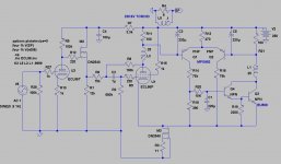
The balance point for the diff pair in the previous circuit depends, as you noted, on the MOSFET turnon voltage Vgs(th). And as this shows wide variation across samples AND drifts downward as the FET warms up, we could have trouble. OK, since we're raiding old stocks of TV triode-pentodes, why not try a sweep BJT? The old BU508 can do 700V [ces]. It'll need a darlington, but why not? For designers focussed on gm, this configuration yields a gm rated in Amperes per volt!
The pic shows a circuit idea for that setup, with 100 Ohm sense Rs, and 3mA per side on the diff stage.
A low pass filter would protect them almost as well. However, an RC filter on the base may suffer from the low impedance looking inward, since the emitter load is so heavy.
But we can adapt the idea and simply bypass the sense resistors: 6V durability for the elkos will do, and 220u rolls off at low enough frequency. This hands us another advantage: we can increase the sense resistor without increasing the losses from the anode currents. Now we can have more headroom on the diff pair, and its temperature effects are almost vanished.
The balance point for the diff pair in the previous circuit depends, as you noted, on the MOSFET turnon voltage Vgs(th). And as this shows wide variation across samples AND drifts downward as the FET warms up, we could have trouble. OK, since we're raiding old stocks of TV triode-pentodes, why not try a sweep BJT? The old BU508 can do 700V [ces]. It'll need a darlington, but why not? For designers focussed on gm, this configuration yields a gm rated in Amperes per volt!
The pic shows a circuit idea for that setup, with 100 Ohm sense Rs, and 3mA per side on the diff stage.
Attachments
The elkos a hardly desirable, but they're not worse here either. They will be consistently polarised in this circuit though.
What we are driving at is a circuit that accurately self-balances the currents in the primary windings. And maintains that balance without fudge-factors for dc screen current, drifts, or temperature effects.
If that works out, you may get a better amp. If not, we spent a few cents on MPSA92s to learn about it!.
Rod,
Your bipolar version looks good to me. Might want to return R16 and R18 to ground as Lars has suggested, instead of the cathodes (and adjust R16 upwards) for improved sonics (no servo currents in the audio path that way, although they are nearly constant and LF here).
Normally, the base current of Q3 would be a concern for fidelity of duplicating the emitter/cathode current, but the Darlington here should be an adequate fix-up if Q4 has high Beta.
Ken,
Obviously some increased complexity here, but this is closed loop current balance versus open loop. Either way, some attention to thermal effects is needed. Either the MPSA92s have to track or the dual cathode Mosfet CCSs have to track.
A tracking current mirror in the cathode CCS, as used before, has some theoretical attraction, but may well be even more tricky to get the thermal tracking right.
Oh, here is a gapped ferrite core suitable for Hall effect current monitoring by the way:
http://www.goldmine-elec-products.com/prodinfo.asp?number=G8912
Could be interesting to see if it could null out any initial hysteretic remenant field in the OT via servo balance. I think Hall effect devices have significant thermal drift problems though.
Don
Last edited:
Well, I have always proposed garter bias for balancing the split tail CCS.
Shoog's bridge keeps the caps polarized with a bleeder, I don't see that
as a problem, or you can bias a single electrolytic with DCV offset as I did.
What issue here did we fix??? Only screen current error at the cathode???
We have fixed it only for DC balance, not for anti-triode AC response to it.
I think we need go back to shunt regulated CCS for that.
I guess you need yet another actively matched CCS for the other screen,
even if there isn't Pentode that side, to keep it all in balance? Same circuit
for cathodes turned upside down, could do for screens.
Attachments
Last edited:
Don, I drew back from returning R16 to ground, since the antitriode emitter would see (ECL86) bias voltage changes (aging, supply voltage, heater voltage) which the base would ignore - and we' risk off-centering the diff. stage, I worry.
Ken, the development is aimed at automatic dc balance in the face of dc screen current, sure, but also bias drifts and aging in the valve. Accurate dc balance is all the more important for toroidal trafos pressed into OTX service, which is the case in the first-post proposal. I think that's a big enough deal to throw some cheap 2 & 3-pin parts at it and see what can be done.
Ken, the development is aimed at automatic dc balance in the face of dc screen current, sure, but also bias drifts and aging in the valve. Accurate dc balance is all the more important for toroidal trafos pressed into OTX service, which is the case in the first-post proposal. I think that's a big enough deal to throw some cheap 2 & 3-pin parts at it and see what can be done.
I agree with your goals. But we don't already have that covered with the split tails?
You went to a unified tail to get rid electrolytics, only to add them back in up top???
You have not answered the question what happens to the AC component of screen
current error at the unified tail. Left uncorrected, it loops back up the folded cascode
into the other end of the OPT. What is that gonna sound like when the plate voltage
dips below the screen, is that consonant with the music signal or something else?
Last edited:
Ken,
One can still put the CCS / zener shunt thingy on the screen with either version to fix the screen current distortion.
The top servo scheme is one more way of balancing the toroid. More is better.
I myself may try the scheme I mentioned earlier of using two identical tubes, and a gm booster on the slave/anti-triode side. Screen currents should balance out DC wise, but I may want to fix them for sonics purposes to see what effect occurs. Seems that Shoog is happy without the fix though.
An opto-servo scheme looks good for conventional center-tapped OTs. Might try that too. A fairly easy mod from the present servo scheme.
And the Hall effect servo has my curiosity up about servo de-magging any OT xfmr at power up if possible, but may not be practical if thermal drift is a big problem. Deserves a thread of it's own. These discussions are dangerous. A half dozen more things to try now, so little time.
Rod,
"Don, I drew back from returning R16 to ground, since the antitriode emitter would see (ECL86) bias voltage changes (aging, supply voltage, heater voltage) which the base would ignore - and we' risk off-centering the diff. stage, I worry."
Ahh, I see. Guess that could be remedied by more current source loads in place of R16, R18, but getting complicated then. Hmm, how about connecting R16 and R18 to a P channel Mosfet follower source, with its gate connected to the cathode line and the drain to ground. On second thought, I think that eats up the M1 threshold voltage for across R16. Oh, could put a bias resistor in series with M3/CCS drain to get some more voltage for the two gate thresholds.
Don
Last edited:
I agree with your goals. But we don't already have that covered with the split tails?
You went to a unified tail to get rid electrolytics, only to add them back in up top???
You have not answered the question what happens to the AC component of screen
current error at the unified tail. Left uncorrected, it loops back up the folded cascode
into the other end of the OPT. What is that gonna sound like when the plate voltage
dips below the screen, is that consonant with the music signal or something else?
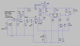
Ken, the dynamic screen current was addressed by Don. Top servo proposal was not just about removing the elkos (though their influence is on output voltage rather than input (grid) voltage in this case).
Blumlein's circuit and split tails may work well, but I don't see how the dc balance in the primary will be better than... 5mA? 10mA? unless you put a trimmer somewhere. Even then, you must keep tabs on temperature drifts. I suspect that toroidal OTX may prefer better than that. The target advantage of top-servo is to reduce dc imbalance to 2mA without having to tweak every time.
Don, how about another way to return servo current to ground... more gain!
Attachments
I myself may try the scheme I mentioned earlier of using two identical tubes, and a gm booster on the slave/anti-triode side. Screen currents should balance out DC wise, but I may want to fix them for sonics purposes to see what effect occurs. Seems that Shoog is happy without the fix though.
You would think that in my setup the screen draw might be very different on each side of the PP since the two valves are performing differently. However I am not hearing any of that nasty core saturation which you would expect from unbalanced current draw. These transformers will go down to 20hz and at those frequencies distortion is very noticable - but it seems not to be there. I will do another listen with some bass heavy tracks just to confirm.
I built a version of the RH807 and tried UL connections to the toroidal OT. I can tell you that even the relatively small amount of DC draw on the screen had horrible effects on the low frequencies. You will be wanting to get the draw balanced to less than 3mA in my opinion. This is why I have a gut feeling that this is going to be a hard nut to crack satisfactorily.
Why not accept the magnitude of the problem and triode strap the pentode. The partial feedback benefit is reduced - but still there. The rest of the amp would then be very simple and you would have achieved an elegant spud amp with a very low output impedance.
Shoog
Why not accept the magnitude of the problem and triode strap the pentode. The partial feedback benefit is reduced - but still there. The rest of the amp would then be very simple and you would have achieved an elegant spud amp with a very low output impedance.
Hey Shoog!
No reason to chicken out
") !
!With the power halved we could as well go SE/Schade and get the same power and exactly the same low Zout.
Also remember the SETOR that Hoktuna and I built. 6B4G, 6L6(tetrode) and 30VA toroid with no screen compensation that plays great!
I´d say if we could get a simpler "anode-servo" without caps, it is the way to go. Still think we need an additional voltagesource of a few volts above B+ to make room for a CCS. Also optocouplers seems interesting.
Otherwise I´ll settle for two MOSFET CCSs, not LM... as they have to high voltage drop, and a cap between cathode and source.
Shoog, have you tried the 15VA Nuvotem/Talemas?
Last edited:
I Aquired a large batch of talema a few years ago. I have used them consistently since then. They are at least 150VAand they have worked wonderfully. I have consistently found that they ring if the primary is wired in the "wrong" direction so testing by ear or scope is needed.
I have used some little Talema's on my headphone amp- and they work well with the headphones, but when driving speakers the bass is sloppy. This is probably due to the gross impedance mismatch.
Shoog
I have used some little Talema's on my headphone amp- and they work well with the headphones, but when driving speakers the bass is sloppy. This is probably due to the gross impedance mismatch.
Shoog
Hey Shoog!
No reason to chicken out
I´d say if we could get a simpler "anode-servo" without caps, it is the way to go. Still think we need an additional voltagesource of a few volts above B+ to make room for a CCS.
Lars, you are a hard man to please.
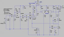
Still, a simple change will give you what you want. Increasing the sense resistors to 330 Ohm drops nearly 12V across them at 36mA. Then the tail will have 11V across it - plenty for your current source. A single transistor current source will be fine.
Increasing the sense resistors makes them easier to decouple, too. 15uF 25V polyester will work fine. You get a very small rolloff below 40Hz, but with toroidal outputs, I think you better keep very low bass out of the amp anyway!
The third advantage of 330 Ohm sensors is the accuracy: with a current source tail and 4300 Ohm "output" resistor, the circuit gives 170V/mA of sense current! so you can put the FET back in and still get much better than 1mA balance.
Attachments
Hey Rod,
For this particular application the LF-rolloff might be a bonus. Was also into single BJT CCS as this seems to be lowest drop as it should work at least down to 2V with a pair of 1N4148 as reference. So wouldn´t the existing 100ohm "anoderesistors" almost do?
How well filtered does the CCS in question need to be? Maybe one could take its B+ a little earlier in the PSU filter chain.
Last edited:
Lars, you could take a separate RC filter off the PSU rectifier if you want higher volts. But so long as you have 150 Ohm or higher sense resistors, you'll have plenty of headroom.
You can have fun in the LTSPICE adjusting the sense resistors and looking at LF rolloff and headroom! The accuracy of balance is also affected, but with a good current source, you will still get better than 1mA balance.
You can have fun in the LTSPICE adjusting the sense resistors and looking at LF rolloff and headroom! The accuracy of balance is also affected, but with a good current source, you will still get better than 1mA balance.
- Status
- This old topic is closed. If you want to reopen this topic, contact a moderator using the "Report Post" button.
- Home
- Amplifiers
- Tubes / Valves
- Spud, Schade, PP, Anti-triode ECL86