cnclld said:How much does this affect the front response below the xo point versus the rear? I guess that could lead to a very strange radiation pattern (not a dipole).
I seem to be the only one on the thread that doesn't thing this alignment is stupid, so take this with a grain of salt.
But it seems that the radiation pattern would be *superior* to a conventional dipole.
Here's why:
In a conventional dipole, there are at least three things affecting the directivity in the room.
- The interference of the front and the back wave create a figure eight pattern which begins at one quarter wavelength. So if you have a 20inch wide baffle, it's going to turn into a figure eight at (13500/20/4) = 168.75hz
- The diameter of the woofer itself will cause the directivity to narrow at one wavelength at the woofer's diameter. So if the woofer has a cone that's 13 inches across, that's (13500/13) = 1038hz
- The shape of the cone itself will narrow the high frequencies, though this will be barely measurable, unless it's a coax. Which this is.
A coupling chamber in front of the woofer is going to roll off the highs, which reduces the effect of item #2. That physical roll off also reduces distortion. Last but not least, the directivity of the woofer will narrow at a much higher frequency, which will make it's response resemble a true figure eight dipole through more of it's range. This should create a stronger null to the sides, reducing the interaction of the room.
I seriously can't find anything NOT to like about this kind of a dipole, except the fact that it reduces high frequency output. Heck, it even looks better. It makes the speakers look like a big ebony slab, instead of a loudspeaker.
Patrick Bateman said:The interference of the front and the back wave create a figure eight pattern which begins at one quarter wavelength. So if you have a 20inch wide baffle, it's going to turn into a figure eight at (13500/20/4) = 168.75hz
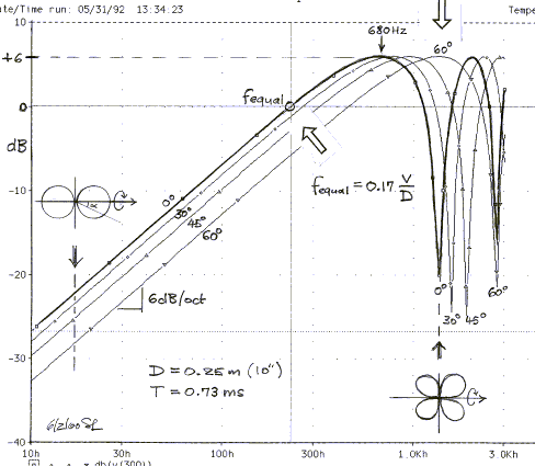
Per Siegfried Linkwitz, the dipole peak is where the wavelength equals the baffle width -- a bit under 700 Hz for a 20" baffle. You'll have a true dipole figure 8 pattern at any frequency below that.
Edit: as chance would have it, the pic on SL's Phoenix models page is for a 20" baffle (D=10").

Patrick Bateman said:Last but not least, the directivity of the woofer will narrow at a much higher frequency, which will make it's response resemble a true figure eight dipole through more of it's range. This should create a stronger null to the sides, reducing the interaction of the room.
From the studies JohnK and others have done, the ideal is to cross below F-peak which is set by the baffle width. If you can't do that, the effective driver diameter should be at least half the baffle width so the driver's directivity simulates the dipole figure 8. Forum member Rudolf has done a lot of experiments verifying those principles.
http://www.audiocircle.com/index.php?topic=64048.0
Looking at it some more, he's only using the bandpass enclosure below 100 Hz so there will be no effect at all on the dipole directivity. The distortion should be lower though as Patrick noted. Excursion is reduced by the bandpass enclosure and it also acts as an acoustical filter of distortion products that are above the bandpass tuning. Pretty clever, really.
Patrick Bateman said:
There's a 48db/octave electronic filter at 100hz.
But the coupling chamber in front of the woofer forms a physical lowpass. If they tuned it at ((2 * FS) / qes), then the reduction in excursion would occur at 53.59hz.
So that seems quite clever. You get a reduction in excursion at the tuning frequency, a reduction in 2nd and 3rd harmonic distortion, and a dipole radiation patterns.
If you're into dipoles, this seems like a serious improvement.
Hey John
Yes, this is true and maybe I didn't see things correctly at first. If this is open back then tuning the front to 50-60 Hz would not only reduce cone excursion, but it would also create a monopole at the tuning frequency - its not a dipole at all. He builds an OB and then turns it into a monopole. Clever, if thats exactly what is happening.
The trouble is that this approach makes no sense in the long run. If this is LPed at 100 Hz then this woofer is nothing more than a classic ported sub. I like subs, just not near the mains. It's a complicated way of doing a system like this. Basically this is a 15" sub attached to a 12" OB coaxial. There is no reason to have the sub in the same enclosure as the mains. There is very good reason not to.
Patrick Bateman said:
I seem to be the only one on the thread that doesn't thing this alignment is stupid, so take this with a grain of salt.
What I ment was that if that thing affects the front response in low frequencies but not similarly the rear response, their phase responses would differ too and therefore the radiation pattern would'nt be a figure eight. The null would'nt be 90 degrees off axis but somewhere else and you would also lose some of the dipole's advantages with room acoustics.
I admit it looks nice and the reduced distortion is an advantage.
With two identical chambers to the front and back that would work.
I have no idea what he's doing for sure. If he has 2 drivers, 2 front ports and 2 back ports, he could be doing a pair of 6th order bandpasses with identical radiation to the front and rear.
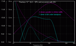
When I first modeled up how it might work, I thought wow, the bandpass is giving you a bunch of free SPL. But then I realized that the bandpass would only give you the equivalent of one box firing forward and one box firing backward to make the dipole. A traditional OB with 2 drivers would have 2 firing forward and 2 firing backward. The sim is still interesting but the clear advantage is gone.
These don't include any dipole effects, just 2 drivers in an infinite baffle vs 1 driver in a 6th order bandpass. The dipole rolloff would be added to this.
Attachments
catapult said:
From the studies JohnK and others have done, the ideal is to cross below F-peak which is set by the baffle width. If you can't do that, the effective driver diameter should be at least half the baffle width so the driver's directivity simulates the dipole figure 8. Forum member Rudolf has done a lot of experiments verifying those principles.
That is only one design philosophy which can be optimized to perform very well. But it is not the only method of designing an OB and in my opinion not necessarily the ideal.
MJK said:That is only one design philosophy which can be optimized to perform very well. But it is not the only method of designing an OB and in my opinion not necessarily the ideal.
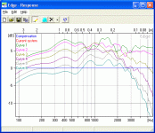
The problem with letting the baffle get too wide and operating above F-peak is you lose constant directivity and you will see the off-axis curves crossing each other. Rudolf has documented it pretty well in various threads here and there. That said, that's only one of many design considerations.
catapult said:
The problem with letting the baffle get too wide and operating above F-peak is you lose constant directivity and you will see the off-axis curves crossing each other. Rudolf has documented it pretty well in various threads here and there. That said, that's only one of many design considerations.
I don't necessarily agree with the results in Rudolf's study.
MJK said:I don't necessarily agree with the results in Rudolf's study.
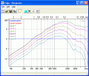
Well, I certainly respect your expertise, but sims in The Edge confirm Rudolf's findings. First a 75mm piston near the top of a wide (60cm x 100cm) open baffle. It starts with the mic at 1m and each curve is moving the mic 30cm to the side.
Attachments
catapult said:
Per Siegfried Linkwitz, the dipole peak is where the wavelength equals the baffle width -- a bit under 700 Hz for a 20" baffle. You'll have a true dipole figure 8 pattern at any frequency below that.
Edit: as chance would have it, the pic on SL's Phoenix models page is for a 20" baffle (D=10").

Ack, I do too much of this in my head.
I said it was 1/4 wavelength, but forgot to consider that it's measured from the midpoint of the woofer. So as you correctly stated, it's 1/2 wavelength, from edge to edge of the baffle. It's 1/4 to wavelength to each edge.
That is particularly handy with a baffle that's not square, as a square or round baffle will be very peaky. The best shape is rectangular, with the woofer offset from the center line.
MJK said:Does your room behave like the EDGE simulation?
No, but it doesn't behave like a Mathcad sim either.
I think the off-axis anechoic response at various angles is a good starting point for correlating measurements with 'how it sounds'. Based on the Harman studies of such things, smooth frequency response is good at any angle and ragged is bad. Flat on axis is good and some HF rolloff off axis is okay.
Patrick Bateman said:I said it was 1/4 wavelength, but forgot to consider that it's measured from the midpoint of the woofer. So as you correctly stated, it's 1/2 wavelength, from edge to edge of the baffle. It's 1/4 to wavelength to each edge.
Actually, it's a full wavelength from edge to edge. If the delay is half a wavelength from the center, and the sources are out of phase, that puts them in phase at the listener.
Are we talking about LF ( < 100 Hz.) in real rooms here? Then directivity has no place in the discussion. Dipole and monopoles in a real room in the modal region do act differently but directivity is not the reason. Directivity at these frequencies is not even a valid concept. It's been pretty clearly established that monopoles, dipoles, cardiods all behave about the same, except for efficiency - directivity is not relavent.
gedlee said:Are we talking about LF ( < 100 Hz.) in real rooms here? Directivity at these frequencies is not even a valid concept.
Hi Earl,
So when I stand between or beside my dipole subwoofers in various rooms and hear a drastic reduction in intensity, than when I was standing a couple meters in front, playing LF <100hz tones. The valid concept that explains this is? The speakers always just happen to be in an anti-node? Psychological?
You have not experienced this (directivity??) with your dipoles in your rooms?
cheers,
AJ
AJinFLA said:
Hi Earl,
So when I stand between or beside my dipole subwoofers in various rooms and hear a drastic reduction in intensity, than when I was standing a couple meters in front, playing LF <100hz tones. The valid concept that explains this is? The speakers always just happen to be in an anti-node? Psychological?
You have not experienced this (directivity??) with your dipoles in your rooms?
cheers,
AJ
I don't have dipoles and I would question your perception. Are you sayiung that this is true for any frequency and any room with any orientation? Or does it happen on occasion.
At 100 Hz, playing a steady state signal, and not too close to the source itself, the sound field will be a complex pattern that has almost nothing to do with the sources free field directivity. By that I mean that on the average, a line along the baffle plane and a line along the axis will see approximately the same spatial fluctuations in the sound field, simple because thecresponse is going to be dominated by the modal response of the room, not the sources response. If the room is has very high absorption at these LFs or you are close to the source, then there will be an effect from the dipole aspect of the source, but not in the reverberant field.
Another way to think about this is to consider the classic method of images solution for a room. There will be so many images, each with a different orientation to the dipole pattern that it will all tend to average out in the steady state. Transients at LFs are, of course, a misnomer since the period of the sound is such that several reflections occur within a single period. Only the steady state in small rooms at LFs can really be discussed.
If you had dipoles pointed along the length of the room, and you went from in front of them to between them then you would hear a dramatic drop in the sound at many frequencies owing to the uniquness of this situation. But random placement of dipoles will not allow this effect to happen.
gedlee said:
Hey John
Yes, this is true and maybe I didn't see things correctly at first. If this is open back then tuning the front to 50-60 Hz would not only reduce cone excursion, but it would also create a monopole at the tuning frequency - its not a dipole at all. He builds an OB and then turns it into a monopole. Clever, if thats exactly what is happening.
The trouble is that this approach makes no sense in the long run. If this is LPed at 100 Hz then this woofer is nothing more than a classic ported sub. I like subs, just not near the mains. It's a complicated way of doing a system like this. Basically this is a 15" sub attached to a 12" OB coaxial. There is no reason to have the sub in the same enclosure as the mains. There is very good reason not to.
If the sound was radiating from a single point in space, then YES, this would be a monopole.
The trick is the spacing between the front and the back, and the width of the baffle.
There isn't a program in the world that can properly model this, with the exception of (possibly) Martin King's worksheets.
But the basic idea is this:
Take a bandpass subwoofer. In a conventional bandpass subwoofer, the volume of the sealed chamber raises the FB to a point above the FS. For instance you might have a 15" woofer with an FS of 30hz, and in a sealed chamber, it rises to 55hz. In a conventional bandpass subwoofer, the front chamber is tuned to the Fb of the rear chamber, or 55hz. So you wind up with a bandpass response that covers an octave and a half, from 35hz to 90hz or so.
In THIS design, the sealed chamber is gone. And the woofer has a QTS that's extremely high, much higher than what would be practical in conventional bandpass. IIRC, the Alpha 15A has a qts of 1.46, whereas a bandpass works well with woofers in the range of 0.3 to 0.6.
So now that we've removed the rear chamber, we have a problem, because the radiation from the back is going to create a massive null with the radiation from the front. It's not going to be a very good subwoofer when there's not output at the tuning frequency!
So that's where the baffle comes in. The baffle delays the front and the rear wave, enough so that the power response is better than a conventional dipole.
As a bonus, the coupling chamber reduces excursion.
It's definitely a complex beast, but there's a ton of advantages:
- Amplifiers are cheap, so the biggest limiting factor to achieve high SPL is no longer the amplifier, it's the subwoofer's excursion.
- You can get a ton of excursion out of a 10" or 12" woofer, but sensitivity suffers.
- You can get the same SPL from a fifteen inch woofer with moderate excursion, but the box is going to be huge.
- The solution from Emerald Physics combines the massive displacement of dual fifteens, with a "box" that has a foot print that's about 1/4 the size.
- As a bonus, the Emerald Physics solutions requires the use of a cheap CHEAP driver. It's $60. To get this kind of SPL with a single fifteen would require a bigger box with twice the excursion. And the woofer would probably cost more.
- The use of dual fifteens instead of a single woofer with higher excursion reduces distortion
- The bandpass design reduces distortion also.
If I didn't have a million* other projects going right now, I'd be building one of these myself.
* http://www.diyaudio.com/forums/showthread.php?threadid=148006
- Status
- This old topic is closed. If you want to reopen this topic, contact a moderator using the "Report Post" button.
- Home
- Loudspeakers
- Multi-Way
- Emerald Physics


