hi Tom...... long time no see........ i worked at APT from 78 to when Frank closed the doors.... maybe my initials are on that test report (WCM). email me if you have time.....
"As I recall it the specification was 0.01% so it is slightly out of that tolerance after 30 years." maybe the wires behind one of the amp modules has moved out of place?
"As I recall it the specification was 0.01% so it is slightly out of that tolerance after 30 years." maybe the wires behind one of the amp modules has moved out of place?
ALL hail the APT, I 've got this baby Smokin' (.0005 -.001% 20k)
wilson mirror level splitter.. Strange "self balancing" LPT ,(you can
put a "deliberate mismatch" for LTP and all is well).
It doesn't seem to have any of the drawbacks of the "blameless"
and sounds like a symasym.
Attached is the latest "bastardization" of the APT. (I'm making
the boards for a triple EF AND a Krill varient).
OS
Attachments
I am very gladdened to see your interest after 30 years!
Hi Tom, you are very welcomed!
Re: Apt 1
tom:
thanks for checking in! i also enjoyed one of these amps some years ago. unfortunately, it was damaged beyond repair during a bad lightning strike.
in addition to some of the info you mentioned sharing, i would be curious to find out how you and the designer (mark?) evolved to the topology that was finally productized. in college, i read your article in electronic design in '81 on the motorola transistors, which mentioned just a bit.
mlloyd1
btw, impressive measurements for a unit unmodified after all these years ...
tomholman said:I am very gladdened to see your interest after 30 years! ...
i remember also a pro-audio variant that was made. the protection/ input board was modified (actually a completely different board was produced) with cannon plugs and a terminal strip for balanced inputs, and holes cut in the rear panel of the belly pan for the cannon plugs. i only saw a handful of them go through the assembly line. they were available by special order only.
Service manuals anyone?
What an auspicious moment to enter this well-frequented thread, with UncleJed and now Mr. Holman present.
I am the very happy owner of some 8+ Apt devices, with a few Apt-1s in the bunch. Can I convince you fellows to post some of the printed info, such as model updates, adjustment procedures, perhaps the service manual itself for the Apt-1?
The information you have shared so far is priceless - thanks from a most grateful aficionado.
Re: Service manuals anyone?
The manuals that came with were pretty much the service manuals
http://www.diyaudio.com/forums/showthread.php?postid=804425#post804425
http://www.diyaudio.com/forums/showthread.php?postid=804922#post804922
dave
Lou914 said:What an auspicious moment to enter this well-frequented thread, with UncleJed and now Mr. Holman present.
I am the very happy owner of some 8+ Apt devices, with a few Apt-1s in the bunch. Can I convince you fellows to post some of the printed info, such as model updates, adjustment procedures, perhaps the service manual itself for the Apt-1?
The information you have shared so far is priceless - thanks from a most grateful aficionado.
The manuals that came with were pretty much the service manuals
http://www.diyaudio.com/forums/showthread.php?postid=804425#post804425
http://www.diyaudio.com/forums/showthread.php?postid=804922#post804922
dave
it'll have to wait a bit. my copy of the sevice manual is in storage. i also used to have a notebook with all of the revisions from 3 to 10. the schematic on the bottom of the amp and in the owner's manual and service manual are from rev 2. most of the revisions were in board layout, though there wer some minor circuit changes along the way. the differences are very minor, and for most purposes the supplied schematic is close enough. some of the components such as the pre-driver transistors have been obsolete for many years. i suppose a replacement could be found for them.
Re: Apt 1
Hi Tom!
I'm sorry I'm so late in seeing your post on this thread. I have always viewed your amplifier as one of ground-breaking performance and engineering insight.
Best regards,
Bob
tomholman said:I am very gladdened to see your interest after 30 years! So I grabbed an un-updated unit we had around and measured it briefly today. I thought it would be interesting to see how it behaves 30 years after it was made!
Apt Power Amp 1 s/n E03049 probably made in 1979. Measured in March, 2009. Unmodified or repaired insofar as I am aware.
Measured with Prism DScope III s/n 00126. This is a digital unit and the sample rate was set at 192 kHz for its FFT. The THD+N band limiting filter was set to its highest value of 80 kHz.
The load was a Dale 8 Ohm 250 W 1% non-inductive wirewound resistor.
The output of 28.28 Vrms is 100 W in 8 Ohms.
The THD+N at 100 W was as follows:
20 Hz 0.0038%
2k Hz 0.004%
10k Hz 0.011%
20k Hz 0.015%
As I recall it the specification was 0.01% so it is slightly out of that tolerance after 30 years.
The noise floor was -78.4 dB below 2.83Vrms or about 3 mV. This too is a little out of spec (from memory) which was -80 dB re 1 W (+20 dB of output for 100W means 100 dB dynamic range, better than true 16-bit audio, but not as good as true 20-bit audio).
So all in all, pretty darn good. The performance was better than the cosmetics as this unit had taken a beating.
It is likely that replacing the smaller electrolytic caps, particularly the power supply ones, would bring it back into spec I'm guessing.
I also grabbed a modern monoblock power amp off the shelf which shall go unnamed for reasons that will get to be obvious. Here is its THD below clipping, at about 45W or so.
20 Hz 0.046%
2k Hz 0.09%
10k Hz 0.63%
20k Hz 0.77%
The noise floor with the level control down was -79 dBr and with it up -72 dBr.
Yikes. What are these "modern" designs all about?
The performance "secret" in the Apt was to design for a low distortion open loop (with a THD+N meter looking at open loop linearity), get it to have low distortion open loop, then close the loop. This means the 2nd stage, the big voltage gain one, dominates, and the cascode connection helped a lot here.
As time goes by I'd be happy to post schematics, layouts, etc., but I don't think it can be reproduced today since some of transistor types are no longer made. It is hard to stabilize a triple Darlington for instance, and it had a 400 MHz ft pre-driver and a 300 MHz driver (both complementary pairs) driving 4 MHz ft output devices so that their poles could be neglected. I don't know where to get such today.
Hi Tom!
I'm sorry I'm so late in seeing your post on this thread. I have always viewed your amplifier as one of ground-breaking performance and engineering insight.
Best regards,
Bob
Apt 1 -manuals and info
Gentlemen, thanks very much for your attention.
I already have the Owners' Manual in both print and pdf form.
While indeed a very thorough examination of the unit and circuitry, it still is missing the critical info so essential to curious half-baked technicians and rank amateur tweakers like me.
For instance, I just fixed a just-bought Apt 1 (red leds shining, no sound) by replacing a bad "Power On" indicator led. That was it ( I am so very proud of myself) - But (!), on the way there, unavoidably, I noticed a couple of other problems: the cause of some internal rattling was that the clip-on heatsinks had shaken off during shipment, and then, the dreaded signs of a replaced output transistor. So this leads me to wondering if the bias and offset are within specs. Offset is around -15 milivolts (easy to measure). Now, I'd like to know the proper procedure for adjusting the bias This information is not in the Owner's Manual but, like the terrific pre-amp version, I'm sure there is a Service Manual somewhere out there!
I found the very useful site:
http://www.audio-circuit.dk/
But the file labeled "Apt 1 Service Manual" is actually a pdf of theOwner's Manual.
Excuse me for not being succinct- perhaps some of you have gone through this!
All insights into this question will be greatly appreciated!
Thanks again.
the proper procedure for adjusting the bias (seems like it was only yesterday.....) :
needed:
rms voltmeter
8 ohm 250W noninductive load
HP-339B distortion analyzer (or equiv)
dual channel oscope
test setup:
amp out to dummy load, oscope channel A, analyzer input, voltmeter
amp in to analyzer oscillator
analyzer residual to scope ch B (vert mode chop, trig source ch A)
settings:
scope A 1V/div
scope B 1v/div (to start with)
horiz 10us/div
osc 20khz 95mV out (adjust for 2.85Vrms out of amp)
amp module bias to minimum (ccw)
analyzer input to 5V input range
procedure:
with 1W 20khz out, let amp idle for 5-10min (this test was done at the factory to an amp still warm from burn-in test, so the warm-up wasn't usually needed)
adjust trig for a stable scope picture with two cycles showing (IIRC it was 1/12 cycles with 2 pos peaks and 1 neg)
adjust scope ch B gain for a clear picture of the residual
the residual will have spikes at zero crossing
slowly increase bias until zero crossing spikes just disappear
that's the bias adjustment
since the amp has been worked on, you might want to run it up to full power at 20 khz and move the wires around that pass behind the amp module boards to null out magnetically induced distortion. we used BIC pen bodies with triangular notches cut in the ends as "wire tweakers" . and then hot-glue (using high temp glue) the wires in place.
you might want to use a small dot of super glue to keep the VAS transistors from dropping their heat sinks
Wow, Uncle Jed, and all from memory!
And I thought it would entail desoldering a resistor or two, measuring the milllivolts and dividing by resistance, etc., etc.
What I'm guessing here is that this very thorough procedure seeks to get precisely at the lowest necessary current with absolutely no excess heat for warming your listening room.
I have no distortion analyzer - I've got the scope and a Sound Technology 1510A- maybe I can get this to produce the test signal... I can just see that curl of smoke looming in the horizon....
Thanks very much! I'm studying this carefully now to see how I can adapt it safely to my present equipment-deprived situation.
Cheers!
Lou
well, as a starting point, you could adjust it to 15-20mV between emitters on an NPN-PNP pair on the output devices with no load/ no signal. it will get rid of most but not all of the crossover notch and provide a temperature stable operating point for the output devices. the distortion method is the proper way to set the bias. the 20mv method is the "safe" way to do it without a distortion analyzer. it biases the output devices for 15-20mA (you have 1 ohm between emitters) idle current.
Thanks for the explanation. Nothing like doing things correctly. Anyway, this alternative is a relatively simple method for checking if we're still somewhere in the ballpark. (Until I borrow that HP Analyzer.)
I see there are two 0.47 ohm resistors in series between Q18 and Q20, as there are between Q17 and Q19, just like you say. Good thing there won't be any soldering involved.
Taking advantage of your knowledge a little more....this unit sure has a buzzy transformer, When you turn on the amp, you can feel the sheet metal vibrate at your standard household line frequency. No shocks, no hum in the signal at all, just a slightly noisy front panel, if you know what I mean. Is this just a mechanical, mounting problem, like something was just knocked out of place? Or could it be the sign of some defective component? Have you ever seen a case like this? No pun intended.
Thanks.
Lou
make sure all of the mounting hardware for the transformer is tight, as well as the front panel screws. another thing to check if it keeps up, there were two different transformers used. the original one was dipped in a silicone/slate mixture, giving the whole transformer a dark grey color, and damping any magnetic "slap" very well. the newer one was dipped in a waxy varnish, and the winding wrap paper is a tan color. these made a little bit of noise, and i guess with time you might get some of the windings or core laminations getting a little bit loose. the only fix would be to re-dip the transformer in varnish. after all this time it's also possible that the big filter caps are drying out and need to be replaced. the rest of the amp could probably do with a re-cap also.
Another APT owner
My original preamp was an Apt Holman and I still own and use it (though not for everyday use; my current system has only one source and it is directly connected to the power amps, so no preamp). I bought another one from a close friend a couple years ago, so now I own two for some reason Both are in great condition and work fine.
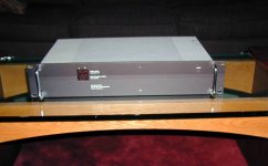
I always liked the Apt One and had friends who owned them. So, I was pleased that I recently had the luck of buying one off the consignment shelf of my local high-end dealer for a good price. It's got a few scratches on the top of the faceplate but is in perfect working condition! I just used it last weekend to provide music for a town event; not the best use for such a classy (and classic) amp but it did the job extremely well!
I especially like the impedance and overload indications, that let you know in real time when you are running over the edge.
Vernon
My original preamp was an Apt Holman and I still own and use it (though not for everyday use; my current system has only one source and it is directly connected to the power amps, so no preamp). I bought another one from a close friend a couple years ago, so now I own two for some reason
Both are in great condition and work fine.I always liked the Apt One and had friends who owned them. So, I was pleased that I recently had the luck of buying one off the consignment shelf of my local high-end dealer for a good price. It's got a few scratches on the top of the faceplate but is in perfect working condition! I just used it last weekend to provide music for a town event; not the best use for such a classy (and classic) amp but it did the job extremely well!
I especially like the impedance and overload indications, that let you know in real time when you are running over the edge.
Vernon
i was in a rock band and we used it as a PA amp with a pair of Peavey cabinets. for venues up to the size of about 100'x100' it was more than adequate. it was pretty "idiot proof" too, we ran it full power into a dead short one night, and all that happened was the rail fuses on the affected channel blew, and the other channel kept on plugging away. after the gig i replaced the fuses and the amp was good to go for the next time......(i also fixed the offending 1/4" speaker plug)
I have an Apt 1 power amp in good condition. I bought it from a local shop here in Tucson about 30 years ago. Has intermittent on one channel. Little green "signal" light (and output from that channel) goes away every now and then. Will often recover with a light knuckle tap to the cover. Probably a solder joint. I just haven't had time to dig into it.
Would be willing to sell to good home. Too many projects in the queue. Contact dave dot milne at honeywell dot com
Would be willing to sell to good home. Too many projects in the queue. Contact dave dot milne at honeywell dot com
Attachments
...... droollllll...... if i had the money right now i would........ i wish i had never sold mine...
the intermitant is probably one of the StakeOn pins which are the terminals all of the 22ga wires are attached to the boards with. , or one of the pins of the 3 color LED (if it's just the LED that's intermittent, and not the audio)
the intermitant is probably one of the StakeOn pins which are the terminals all of the 22ga wires are attached to the boards with. , or one of the pins of the 3 color LED (if it's just the LED that's intermittent, and not the audio)
Last edited:
- Home
- Amplifiers
- Solid State
- APT 1 power amp – undeservedly forgotten