G.Kleinschmidt said:
Current balance in the LTP (without a current mirror) has nothing to do with Vbe matching of the LTP transistors. It is determined by how accurately the resistor connected between the base and ther emitter of the VAS transistor forces the LTP's active leg current to equal 1/2 the LTP tail current.
Secondly if an emitter follower is used to buffer the VAS the imbalance caused by the VAS/EF base current drops to insignificance (even with a LTP tail current as low as 1mA, which would typically give a mediocre slew rate, and doubly so without a current mirror).
Cheers,
Glen
Glen is exactly right. The proper approach is to use a three-transistor current mirror (i.e., with the "helper" transitor) feeding a VAS with an emitter follower in front of it (some would call this a Darlington VAS transistor). With this arrangement, the LTP is remarkably well-balanced, especially if the degeneration resistors are well-matched and there is a significant amount of emitter degeneration in the current mirror. It also helps to have both current mirror transistors matched well in Vbe and beta, but this is not super critical.
Cheers,
Bob
cbdb said:best design= low dist. flat freq response high enough slew rate etc and I do believe it has to sound "good" but this is so subjective its hard to quantify, espescially for DIY guys. Does adding a few 3 dollar Ic really going to add that much $$$ to an amp with a 80 dollar transformer?
Well, if you are going to build a few of them, it adds up, no? If you can achieve all of your requirements for a "best design" with some 5 or 10 cent discretes, why not? It has been done before.
As I said earlier, I see no imbalance in my cascoded LTP using a CM with good but un-matched devices. As pointed out by Glen above, the current drawn from the LTP into an EF VAS has an insignificant effect on the LTP balance.
I'm just learning here and to keep myself interested in this subject (I am interested) I contribute. Take what I say as comment from the peanut gallery.
")
Glad to see this continuing as a lively discussion.
Right you are ,MJL, the LM49810 has full widlar CM's and
precision current sources all around.
I'm already there. I just got my amp done , and while the iron
was still hot ,I tried the diode, buffered widlar (SMD device)
and compared it to the standard CM.
Heres what I tried it on...
Just finished Frugalamp..
I know MJL hates LED's but they keep dummies like me from
getting zapped...
What I noticed between the 3 configurations was:
1. after biasing I proceded to hook it up in a sufficiently ignorant
manner to my speakers,the"self clone" sounded great (of course) . (.01Ma CM balance 2.2Ma/per side)
2. Added the "halcro diode" ,I really didn't notice any change
with rock or HT but a subtle increase of depth and imaging
from my classical collection.
3.With the buffered widlar mirror I could notice a difference
with any content..!! So I tried the classical and I am
impressed.. it is the eerie kind of effect I wanted.
And of course to end the session I tried the Sanyo HT receiver to
balance out my opinion.
I agree with Bob and think the 3 tranny version blows away the
competition..
OS
By MJL : why not one of those entire front ends from National the LME49-whatever? Those are only $14 (here)
Right you are ,MJL, the LM49810 has full widlar CM's and
precision current sources all around.
By sandy K : Instead of just simulating it, why not try it ? You may be surprised.
I'm already there. I just got my amp done , and while the iron
was still hot ,I tried the diode, buffered widlar (SMD device)
and compared it to the standard CM.
Heres what I tried it on...
Just finished Frugalamp..
An externally hosted image should be here but it was not working when we last tested it.
I know MJL hates LED's but they keep dummies like me from
getting zapped...
An externally hosted image should be here but it was not working when we last tested it.
What I noticed between the 3 configurations was:
1. after biasing I proceded to hook it up in a sufficiently ignorant
manner to my speakers,the"self clone" sounded great (of course) . (.01Ma CM balance 2.2Ma/per side)
2. Added the "halcro diode" ,I really didn't notice any change
with rock or HT but a subtle increase of depth and imaging
from my classical collection.
3.With the buffered widlar mirror I could notice a difference
with any content..!!
So I tried the classical and I amimpressed.. it is the eerie kind of effect I wanted.
And of course to end the session I tried the Sanyo HT receiver to
balance out my opinion.
I agree with Bob and think the 3 tranny version blows away the
competition..
OS
ostripper
Assuming you are using the usual LTP and CM configuration etc as used by Doug Self etc. For best results when using the diode, you need to slightly adjust the emitter resistor value of the VAS
so that you get as close as possible to 0mV between the 2 collectors of a very well balanced LTP when at normal operating temperature. Explanation is below, however only thing changed since 1987 is that there are now several DIYAudio members in Australia and U.K. ,who can attest that this actually makes an improvement as claimed. This method has also been used successfully by vhfman who has posted recently.
In 1987 , I wrote a letter to Neville Williams, the editor of Electronics Australia.
I asked : Why in a preamplifier with a very closely matched differential pair, did the sound after a period of time, exhibit a much better soundstage, and sound "sweeter". The marked improvement did however slowly disappear again.
I then stated that on every occasion that I became aware of this happening, I took DC measurements, and on EVERY occasion
the difference in voltage between the differential pair collectors was <5mV (!)
The editor did not reply.
Congratulations on the successful build OS! Fast too.
So, you actually heard a difference?
That means you did something else wrong
Looks good. I'll stick (for now) to my faulty amateur 2 transistor one.
Sidenote: For the second time I have seen my signal ground isolation resistor go open for no apparent reason (see my thread). You might want to add opposing diodes in parallel to your own.
Bob Cordell said:
Glen is exactly right. The proper approach is to use a three-transistor current mirror (i.e., with the "helper" transitor) feeding a VAS with an emitter follower in front of it (some would call this a Darlington VAS transistor). With this arrangement, the LTP is remarkably well-balanced, especially if the degeneration resistors are well-matched and there is a significant amount of emitter degeneration in the current mirror. It also helps to have both current mirror transistors matched well in Vbe and beta, but this is not super critical.
Cheers,
Bob
However, the situation changes with signal voltage due to the VAS cdom. I think this is the issue raised by Andrew T.
In other words the VAS implementation and value of Cdom are capable of limiting the CM high frequency performance regardless of what lenghts you go to in matching devices and idle currents.
ostripper said:Glad to see this continuing as a lively discussion.
Right you are ,MJL, the LM49810 has full widlar CM's and
precision current sources all around.
I'm already there. I just got my amp done , and while the iron
was still hot ,I tried the diode, buffered widlar (SMD device)
and compared it to the standard CM.
Heres what I tried it on...
Just finished Frugalamp..
An externally hosted image should be here but it was not working when we last tested it.
I know MJL hates LED's but they keep dummies like me from
getting zapped...
An externally hosted image should be here but it was not working when we last tested it.
What I noticed between the 3 configurations was:
1. after biasing I proceded to hook it up in a sufficiently ignorant
manner to my speakers,the"self clone" sounded great (of course) . (.01Ma CM balance 2.2Ma/per side)
2. Added the "halcro diode" ,I really didn't notice any change
with rock or HT but a subtle increase of depth and imaging
from my classical collection.
3.With the buffered widlar mirror I could notice a difference
with any content..!!
impressed.. it is the eerie kind of effect I wanted.
And of course to end the session I tried the Sanyo HT receiver to
balance out my opinion.
I agree with Bob and think the 3 tranny version blows away the
competition..
OS
http://en.wikipedia.org/wiki/Groupthink
Non-Group Mirror
Lineup,
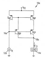
Here is something different (non-group) idea. Everyone seems to be hung up on Widlar Mirrors.
Taken from the following patent,
http://www.google.com/patents?id=0tAgAAAAEBAJ&printsec=abstract&zoom=4#PPA1,M1
This is a great read as it includes numerous examples of different mirrors.
Regards,
Jam
Lineup,
Here is something different (non-group) idea. Everyone seems to be hung up on Widlar Mirrors.
Taken from the following patent,
http://www.google.com/patents?id=0tAgAAAAEBAJ&printsec=abstract&zoom=4#PPA1,M1
This is a great read as it includes numerous examples of different mirrors.
Regards,
Jam
Attachments
VHF man said:
However, the situation changes with signal voltage due to the VAS cdom. I think this is the issue raised by Andrew T.
In other words the VAS implementation and value of Cdom are capable of limiting the CM high frequency performance regardless of what lenghts you go to in matching devices and idle currents.
Yes, I have noted many times that the Miller capacitor can introduce some degradation, such as a loss of HF PSRR. I was referring above to the dc balance situation.
I generally prefer to use input Miller compensation, where the Miller capacitor is returned to the inverting amplifier input of the LTP. The proper stabilization of the inner loop formed by this approach is not as straightforward as simple Miller compensation, however.
Cheers,
Bob
Re: Non-Group Mirror
My first impression of this mirror is that it is sub-optimal in a couple of ways. Just because something shows up in a patent doesn't mean it is any good.
This looks like a helpered current mirror with a poor man's attempt at making its output sort of a quasi-cascode.
First and foremost, it brings the collector-base nonlinearity right into the picture. Secondly, it looks like it introduces current imbalance via the base current of the quasi-cascode transistor.
Maybe I missed something here. That's just my first impression.
Cheers,
Bob
jam said:Lineup,
Here is something different (non-group) idea. Everyone seems to be hung up on Widlar Mirrors.
Taken from the following patent,
http://www.google.com/patents?id=0tAgAAAAEBAJ&printsec=abstract&zoom=4#PPA1,M1
This is a great read as it includes numerous examples of different mirrors.
Regards,
Jam
My first impression of this mirror is that it is sub-optimal in a couple of ways. Just because something shows up in a patent doesn't mean it is any good.
This looks like a helpered current mirror with a poor man's attempt at making its output sort of a quasi-cascode.
First and foremost, it brings the collector-base nonlinearity right into the picture. Secondly, it looks like it introduces current imbalance via the base current of the quasi-cascode transistor.
Maybe I missed something here. That's just my first impression.
Cheers,
Bob
Mr.Cordell,
I was hoping for more input on different kinds of mirrors especially the Widlar and Wison.
Thanks for your insight into the circuit posted, I see your point on where the weaknesses may be.
Do you have a preffered type of mirror?...............
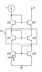
or how about this which appears be some form of cascoded Widlar/Wilson Mirror?
Regards,
Jam
I was hoping for more input on different kinds of mirrors especially the Widlar and Wison.
Thanks for your insight into the circuit posted, I see your point on where the weaknesses may be.
Do you have a preffered type of mirror?...............
or how about this which appears be some form of cascoded Widlar/Wilson Mirror?
Regards,
Jam
Attachments
Ostripper as you are the one with the iron in the hand, could you try that widlar again but instead of connecting the collector to ground connect it instead to ltp current source, (between the two ltp emitter resistors) , should have some effect too. This way the helper transistor will have constant current source with the advantages of a high impedance node.
Jam, a combination between a widlar and the three transistor wilson gives quite a big performance jump and sounds much better than just a standard CM but then again it was in a design where I settled for using cascoded mirrors which doesnt have ltp. It would be interesting to hear results with a blameless so maybe ostripper can test these things on his amp. I connect the widlar as the above post though.
BTW Bob I simmed that patent circuit and it certainly outperforms all the others. After simming the combination above the two perform on par. I cannot comment on the sound of the patent circuit but Ive found that any combination or the trick like sandyk uses to bringing better balance between the two halves of ltp have positive effect on sound, that is on a blameless.
BTW Bob I simmed that patent circuit and it certainly outperforms all the others. After simming the combination above the two perform on par. I cannot comment on the sound of the patent circuit but Ive found that any combination or the trick like sandyk uses to bringing better balance between the two halves of ltp have positive effect on sound, that is on a blameless.
CM Discussion
homemodder.
I believe that it isn't the added diode in one method, that makes an improvement due to any effect on the CM, but due to the added voltage drop in the unloaded side that brings the currents through both sides of the LTP much closer.This will also be true with many CFP input designs. Incidentally, the reason I now use the Series Schottky diode plus the 20T trimpot, is that the vertically mounted Schottky diode thermally tracks the VAS, which in a preamp or Class AB, enables maintenance of a +-2mV difference between the collectors of the closely matched LTP devices. (yes, you can hear the difference with this degree of matching) Even with a 15W /Ch. Class A design ,with a total dissipation of around 100W, the tracking will stay within +-5mV if carefully adjusted when warm.
"Blameless" designs, with all due respect to the very talented Douglas Self, are often reported to sound bland, and with a small soundstage. Balancing the front end as described, (and I am sure that there are also even better ways to do this) will transform a "Blameless" design into an amplifier with a truly excellent soundstage, and with heaps of separation between the vocalists and instruments. IMO, Douglas Self has of course done all the hard work, by getting the Blameless to such a state of perfection, that these changes are readily apparent.
SandyK
- Home
- Amplifiers
- Solid State
- Current Mirror Discussion