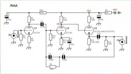
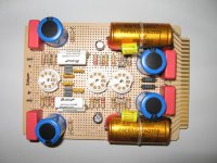
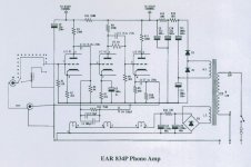
It is mounted using point to point. Here the preamp section. It used normal carbon film resistors, Nichicon HV caps bypassed by Wima MKP for the supply. The passive feedback network used Caddock MK132 resistors and 1% Silver Mica caps. The coupling caps are a little bit more fancy. I used RelCap for the first stage, then Jensen paper in Oil, bypassed by a small 0.1uF Musicap, for the final output cap.
The final tube can be a 12AT7 or a 12AU7. It is selectable by a jumper that change the cathode resistor, see schematic.
The final tube can be a 12AT7 or a 12AU7. It is selectable by a jumper that change the cathode resistor, see schematic.
Attachments
And the supply schematic. It is using a EZ81 Tube rectifier and CRC pre-filter for the HV. The filaments are DC, 12V using Soft recovery rectifiers and LV regulator IC. The Filaments voltage is lift over ground by about 30V, using a voltage divider connected to the HV section for better noise reduction. I may use an adjustable potentiometer instead of R309, R310 as some users reported even better adjustable noise reduction.
The actual supply schematic is using only CRC filtering for the HV. I'l try to use dual mono Shunt HV Regulator using my own PCB.
The actual supply schematic is using only CRC filtering for the HV. I'l try to use dual mono Shunt HV Regulator using my own PCB.
Attachments

Hello together,
I´m from Germany and I´ve been reading in this forum for quite a while. I haven´t posted anything yet because my knowledge is still limited. Not to mention my lousy grammar")
But this thread seems to be perfect for me because I built an EAR834P clone a couple of years ago myself. I noticed a mistake in all the schematics I saw. There should be an additional RC filter between the second stage and the cathode follower. At least there was one in the original EAR834P I had.
This is the Link to a side with my version. Unfortunately for all of you, it is in German but I think the schematic speeks for itself. It is based on the original unit and Thorstens suggestions.
Kind regards,
Martin
I´m from Germany and I´ve been reading in this forum for quite a while. I haven´t posted anything yet because my knowledge is still limited. Not to mention my lousy grammar
But this thread seems to be perfect for me because I built an EAR834P clone a couple of years ago myself. I noticed a mistake in all the schematics I saw. There should be an additional RC filter between the second stage and the cathode follower. At least there was one in the original EAR834P I had.
This is the Link to a side with my version. Unfortunately for all of you, it is in German but I think the schematic speeks for itself. It is based on the original unit and Thorstens suggestions.
Kind regards,
Martin
Hi MartinR. Thanks a lot for the info. Indeed I found your superb built last year. Great site and gorgeous EAR834P clone. Thanks for the comment. I found the original EAR834P in their user manual but it has not this RC filter, see the included schematic. It was not mentioned either by Thorsten.
But you said it was in the original EAR834P you had? It may well be the case, manufacturers are notorious for their incorrect or incomplete diagrams. It may well be also a design change down the road.
If you say it was there, then I'll add one as well.
What about the 100R, 3.3M resistors at the cathode follower input. There were rmoved by Thorsten.
Attachments
Hello Algar_emi,
I changed the position later. The 100R is directly at the grid and the 3M3 upfront. I also put another 100R between cathode and coupling cap, cathode resistor to be on the safe side.
Kind regards,
Martin
What about the 100R, 3.3M resistors at the cathode follower input. There were rmoved by Thorsten.
I changed the position later. The 100R is directly at the grid and the 3M3 upfront. I also put another 100R between cathode and coupling cap, cathode resistor to be on the safe side.
Kind regards,
Martin
Hi analog_sa. I may use Air caps, I got a nice kit of these around. I'm starting with the silver mica for now.
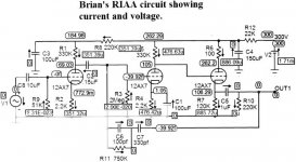
My supply is putting more voltage than 305V, I have 342V (my transfo is specs for 110V, but the line supply 120V, so...
The two first stages have about the same voltage readings, but the last tube cathode has 195V (68K resistors, ECC82,12AU7 tube) instead of the 120V measured by others. Any suggestions?
Here all my readings. Any comments would be appreciated.
Attachments
Hello Algar_emi,
Yup, that´s pretty much how my unit looks like. I only used 18K and 180K in the filters to match the voltages of the original. But the voltage on your cathode follower seems a bit of. You should have around 10V more on the cathode than on the grid. Is the tube ok? The current should be around 1.8mA.
Kind regards,
Martin
Here my schematic modified using yours. Is it Ok?
Yup, that´s pretty much how my unit looks like. I only used 18K and 180K in the filters to match the voltages of the original. But the voltage on your cathode follower seems a bit of. You should have around 10V more on the cathode than on the grid. Is the tube ok? The current should be around 1.8mA.
Kind regards,
Martin
- Status
- This old topic is closed. If you want to reopen this topic, contact a moderator using the "Report Post" button.
- Home
- Amplifiers
- Tubes / Valves
- My own version of the EAR 834P Clone