Hafler Humm
Just did a quick test. The excursions are very slight, almost imperceptable. (both channels) The power-down humm is present on both channels equally loud and equal duration. The amp sounds finw but deterioration may be gradual and I have no real test equipment. RE: DC voltage... Testing w/ a cheap VOM with speakers attached...no signal input to amp..the best I can interpolate my meter is the DC is under 250mills. (10VDC full scale is best resolution this meter will give me)
Just did a quick test. The excursions are very slight, almost imperceptable. (both channels) The power-down humm is present on both channels equally loud and equal duration. The amp sounds finw but deterioration may be gradual and I have no real test equipment. RE: DC voltage... Testing w/ a cheap VOM with speakers attached...no signal input to amp..the best I can interpolate my meter is the DC is under 250mills. (10VDC full scale is best resolution this meter will give me)
Well, I guess that if the cone movement is slight and the amp sounds fine otherwise, I would not worry too much about it. However, it would be prudent to recap it (new electrolytics) if you plan to keep it.
The MC PA3-B cards I have here sound superb. Each iteration that John Hillig produces is an improvement over the previous version so I would believe that the PA3-C sounds even better. This is not a cheap mod but it creates for you an entire new amp. The "sound" of an amp is in large part a function of the circuit on the PCB. Your present filter caps are 25 years (or more) old so I would recommend also getting the MC power supply cap upgrade.
As you can see the manual is very thorough. If you are handy with a soldering iron you might consider installing all of this yourself.
To measure DC offset in your present amp you need to disconnect signal and speaker wires and use a DC meter that can read millivolts. Your amp should not have more than 50 millivolts of DC offset (preferably less than 20 mv) as measured across the terminals for the speakers on the back panel.
What are the values of the speaker protection fuses on the back panel? The MOSFETs are rugged devices and rarely fail unless really seriously abused. If the amp is properly fused (see its manual) then it will last a long time. But, based on its serial number you mentioned I think your PCBs are brown phenolic board. This PCB is not good for doing mods as the traces on its back side are just glued on and easily come lose. The last version of the DH-200 had PCBs on epoxy fiberglass boards (gray green in color) with through plated holes. These PCBs can withstand some modifications by us amateurs with our sloppy soldering skills.
DH-200 mods and 3rd MOSFET pair
My thanks to FAB and others who posted recently about adding a 3rd pair of MOSFETs and increasing the drive current to them.
Yesterday finished the DH-200 pair of mono blocks. Each channel now has 42K+42K uF (84K total) of old NOS Sangamo caps rated at 90 WVDC and each one of them is bypassed with a 1400 uF electrolytic.Each channel has five 0.1 uF polypropylene film caps on the PCB to bypass the electrolytics and PS rails, plus 2 more of the same type caps to bypass the drains at the heat sink. All of this gave an excellent sound. Boosting the driver current to 160 mA and adding the 3rd pair of MOSFETs gave the sound a more solid character and better bass. Then, I replaced each channel's C1 (10 uF electrolytic) with a 4.1 uF + 1.2 uF combo of Solen polyrpop film caps. This last mod was the icing on the cake. It did make a considerable difference!
I am thoroughly enjoying listening to CDs and would characterize the sound of these mono blocks as detailed, even clinical, but never harsh. Mids and highs are sweet sounding. For the first time I think I understand what some golden ears call "round" sound, "round" notes. The sound is there, there is more "there" there now, and sometimes I can even hear hall ambiance and attack decay never noticed before. The sound stage is large but not bloated and each instrument and performer stays in place regardless of changes in dynamics. For the last 5 years the Musical Concepts modded amp as been my reference. Now, I think I will go with the DH-200 mono blocks for a long time. They are that good! Eventually I will compare the MC amp with the DH-200 amp. If my audio memory is valid I think the two amps will sound similar, maybe slightly different, but neither will be better. And, this modified DH-200 pair of mono blocks was a lot cheaper than the MC modded amp.
I mispoke above when I wrote:
I meant to write that by reducing R31 from 220 ohms to 160 ohms driver current was increased.
Obviously my fingers got disconnected from my brain.
Boosting the driver current to 160 mA
I meant to write that by reducing R31 from 220 ohms to 160 ohms driver current was increased.
Obviously my fingers got disconnected from my brain.
I can't seem to find my dh200 schematic , can anyone tell me what the equivalent designation for R31 is in the dh220?
I assume we are talking about the 220 ohm between the emitters of the driver transistors.
You got my interest Iam going to drag my dh220 out of storage and try adding another set of mosfets.
I assume we are talking about the 220 ohm between the emitters of the driver transistors.
You got my interest Iam going to drag my dh220 out of storage and try adding another set of mosfets.
Thanks Dick , my face is red if I had read back in the thread I would have seen it.
I still say the most obvious improvment that can be made in the Haflers is to replace the wimpy 10k uf filter caps with 30k uf or more.
and increasing the standing bias as much as you dare within the heatsink limitation.( oops of topic -sorry)
iam wondering with the added pair of outputs and increased driver current If the dh220 will do better on my 4.85 ohm Magneplanar's.
Damn another project on the list!
Tweaks
Hi Amp-Guy Many many years ago I cranked the bias up on my DH100 to improve sound. So far all has been well until I recently had to relocate the amp into a cabinet (furniture). While I put a small fan providing some cooling...after the amp has been played LOUDLY cranking for a half hour or more she shuts down (thermal overload.) What is the recommended bias (factory). What is the audiophile choice bias...what is tghe max you shouldn't cross. Oh yes...I forgot where and how to measure the bias current. Can you help?
ALSO. What caps do you recommend for a retrofit. (Make and model #s.)
Hi Amp-Guy Many many years ago I cranked the bias up on my DH100 to improve sound.
Do you mean DH-200 or DH-220?
Pages 10 and 11 of the DH-220 manual describe how to set Bias and correct DC offset. The manual states 275 mA for bias (idling current).
The seminal article on POOGing the Hafler amp (the Audio Amateur ca. 1983 by Jung and Marsh) stated 100 mA is the sweet spot for each MOSFET, so 4 Mosfets X 100 mA plus 50 mA for the circuit card adds up to 450 mA per channel.
Others state no device should be too hot to hold in your fingers for more than 5 seconds (usually about 65 degrees celcius). These amps do run very warm and putting them into anything but a large cabinet is to be avoided. They need to "breathe."
Also consider that higher bias = higher temps that = higher temps inside the cabinet where other components are located. One might get the very last tad of sound improvement with higher bias but be shortening the life of the amp.
interesting that the pooge article recommends 450ma , that is about the point that I like to set the 200-220 to. if memory serves mine is set to 500ma. which is probably on the edge.
i had a plastic cased vcr above it which became distorted from the heat to the point that the door wouldn't open.
I whole heartedly agree with what dick has just said, this is good advice with any highly biased power amp.
I skipped subscribing to TAA in 1983 so I haven't read the POOGE
articles
i had a plastic cased vcr above it which became distorted from the heat to the point that the door wouldn't open.
I whole heartedly agree with what dick has just said, this is good advice with any highly biased power amp.
I skipped subscribing to TAA in 1983 so I haven't read the POOGE
articles
Adjusting Process
My manual (DH200) does NOT show a method of bias adjustment. When I bought the kit the bias was pre set at the factory. I read decades ago how to tweak but no longer have those details. Where does one "stick the probes" of a DMM to read the bias current? Is there any lit on the net that shows this detail? If not...I'll just have to provide more cooling air! (Hate that aux fan noise !)
My manual (DH200) does NOT show a method of bias adjustment. When I bought the kit the bias was pre set at the factory. I read decades ago how to tweak but no longer have those details. Where does one "stick the probes" of a DMM to read the bias current? Is there any lit on the net that shows this detail? If not...I'll just have to provide more cooling air! (Hate that aux fan noise !)
How to set Bias
Both the DH-200 and DH-220 set the bias in the same way. Here is a quote from the DH-220 manual:
Bias
Remove the B + fuse F2. This fuse is in the line from the ’ +’
capacitor terminal to hole #3 on the board. Connect an
ammeter’s ' + ' !ead to the fuse clip nearest the large filter
capacitors. Connect the’ -’ lead to the other side of the fuse clip.
Avoid intermittent connections, and do not short the leads
together. Turn the amplifier on, and if possible adjust the line
voltage to 120 volts. Adjust P2, near the middle of the board, to
275 mA. Turn the amplifier off, and when the current drops to
zero, then remove the ammeter and replace the fuse.
Of course the DH-200 only has one adjustable pot so you would adjust P1. You should make this adjustment with input to the RCA jack and outputs to speakers disconnected. Your meter must be able to read 500 mA of current. As you adjust the bias let each change "cook" for a few minutes until the amp's temperature stabilizes to the new/changed setting.
CAPS
Thanks for that info on setting the bias. I would also like to change out the big can (10KuF) caps in my DH200. What is the recommended replacements; where can I get them? ( how expensive?) Are they a simple drop-in or will I need to do mechanical mods to make them fit ?
Any others I should consider changing out while I'm in there?
THANKS
CAPS
You should try the search function on DIYaudio. The subject of caps has been discussed many, many times over. For starters check (on this thread) posts 579 and 647 through 650.
My opinion is that the best is the $90 cap package from Musical Concepts.
But, many experts here say most any good quality computer grade cap will be OK for the power supply. Beware of caps whose body are the right size but do not have low profile posts. Also, some experts have commented about also including a 500 uF to 1000 uF quality (low ESR) electrolytic in parallel to the larger caps.
You should also consider installing 6800 ohm 2 watt bleeder resistors across the terminals of each PS cap.
Re: DH-200 mods and 3rd MOSFET pair


I am glad you found your nirvana.
Thanks for sharing your experience with us.
Dick West said:My thanks to FAB and others who posted recently about adding a 3rd pair of MOSFETs and increasing the drive current to them.....
.......
I am glad you found your nirvana.
Thanks for sharing your experience with us.
Hi everyone, this is one of the most interesting threads I have seen on the Halfer DH200 amps by far, with plenty of good input. I was wondering if anyone has had a chance to compare a Pooge2 modified DH200 against a DH200 with musical concepts boards? I have an 80s modded Pooge2 unit which is my current favorite amp for my mid/high towers, even when compared against other decent amps that I have/had such as Threshold S/300 Series 2, S/500e, Hafler DH220 and 9305 (all stock). All of the amplifiers listed have the stock oem caps, except the modded DH200 which has large Mallory units, but they too are also from the mid 80s. I find the difference to be quite noticeable, the sound stage on the modified DH200 is much more forward, and very revealing on small details such as artists breathing, fingers sliding on guitar strings etc. Needless to say the Threshold units win hands down when it comes to power though, and their build quality is over the top, I never get tired of looking into them. I am using my S/500e to power my bass towers, which it does so with effortless grace. I have an S/350e to try, but need to change cable ends or speaker terminals in order to test it. Another question that comes to mind is, what kind of difference is noted when aging capacitors have been swapped out with proper replacement or upgrade units? Can anyone relate their firsthand experience with the cap change? The monoblock Halfers with the extra mosfets also looks very interesting as well as cost effective, something I would like to try if I can get my hands on some additional units. ")
Hi msb64
I think that Dick West has already tried the Musical concept board but I am not sure if he's tried the Pooge2 - which is the regulated front end supply I believe. I understand that you share my findings about the improvement due to the regulated supply...
For the caps, if you refer to the big ones used in the main supply, one good improvement for bass I noticed was using 2 diode bridges and 4 x 14k uf: 1 bridge and 2 x 14K uf to power each channel. See example at: http://fabaudio.googlepages.com/HPIM1301.JPG/HPIM1301-full;init:.jpg
Good luck
Hi Fab
I am going from memory and it has been awhile since the mod (mid 80s) of my DH200, but I do recall most of what I did.
I am almost embarrassed to say that I actually did not incorporate regulation, or a soft start circuit back then, both of which I will definitely look into now.
I followed pretty much all of the other suggestions in that article, metal film resistors, Wonder Caps throughout, gold plated RCA and Binding Posts, minor circuit changes etc. and even a modest attempt at Litz wiring too.
I went a little further on the power supply though, I moved all of the AC components out of the amp into a separate enclosure. My plan was to try and keep the amp as quiet as possible. I installed 2 Hammond 180M90 torroids in parallel for increased current capacity (total 6.6A), added 2 Mallory 37,000 MFD caps along with the stock Sangamo 10,000 MFD caps, installed WonderCap 4 ufd and .01 ufd bypass caps on these, and also installed the beefiest rocker power switch I could find at the time. I fabricated a 14 gauge umbilical cord to connect the units using military grade screw/locking connectors.
The DH200 is the first kit amp I ever built, and this was also the first piece I ever modded so I would like to make a better effort now.
I want to keep this one as is for comparison purposes, and build a couple of more units, one for me and one for my brother.
One of them will definitely have musical concepts boards in it and the other I was planning on more or less following the Pooge 2 upgrade somewhat with modern components.
If I can get my hands on a couple more DH200s, I would definitely like to try the monoblock setup of Dick's. It would be nice to do up custom enclosures to isolate the power supplies in each. Each side with a metal divider built in to shield the supply section. Seems like a good fabrication project too.
I think there are still a lot of people who don't know how good these units can sound when modded, you have to actually here it yourself to believe it. I have some parts on order, can't wait to get started on one of them. I might have to part with some equipment though to pay for the musical concepts components, and that is always hard to do.
By chance does anyone have a good source for the large Mallory caps or a suitable equivalent?
I still have my 1984 receipt from Cam Gard Supply, I paid $46.88 Cdn for each cap back then, I imagine they have gone up a bit since then.
The Hammond torroids were $61.81 Cdn each
Mike
Attachments
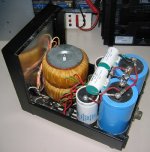
Now that's what I call modding, you must have at least 6 extra little pc boards in there. Getting that all to fit in the stock enclosure is a major feat in itself, never mind the actual sound improvements. It would also make for a heck of a schematic too for the system. The bus bar is a neat idea, reminds me of electrical panels.
- Home
- Amplifiers
- Solid State
- Hafler DH-200/220 Mods