Sigurd,
(As a matter of fact, it was insightfully pointed out by Hiraga himself. That man is obviously right about everything).

They work, but perform poorly, should be the same type as suitable for voltage amplification. You don`t use FETs in VAS. It´s about conduction losses, Gm and slew rate.Here we disagree. JFETs work fine for cascode work. I have many amp with JFETs for cascodes. Even MOSFETs could be used.
(As a matter of fact, it was insightfully pointed out by Hiraga himself. That man is obviously right about everything).
It`s a voltage reference. High dynamic impedance current sources in conjunction with low dynamic impedance voltage references form effective filters. The voltage at any sensitive base or gate should be clean. Ripple and noise don`t sound nice (much worse than THD).I guess your 5V "Zener" is not a Zener but something else, right?
Lumba Ogir said:Sigurd,
zeners are nasty noise generators causing ugly distortion.
They stay on the top of my blacklisted parts toghether with ceramic capacitors and opamps.
IC voltages references should be used.
LEDs are noisy too, with a zener-like behavior.
Hello, Lumba
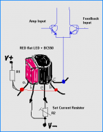
I am not at all afraid of using RED LED for V-Ref.
They are excellent when wanting a simple + good solution
and not very noisy, in my opionion.
( See Christer, Sweden, investigation link below )
One of the positve things, is when they are put in close contact to the transistor body,
when used as a constant current source, RED LED have a fair temperature compensation.
Preferably I use flat 5mm RED LED, with the flat surface tightly attached
to the flat surface of the TO-92 transistor body.
See pratical example how to in my attached picture.
diyAudio 2004-06-10, Christer:
Some noise measurements for LEDs and zener diodes
Attachments
Lineup - I agree with you. LEDs are superb voltage references in a CCS,
but also when one wants to have a super-low-noise voltage source.
If anyone knows of a more low noise voltage source than a blue LED, do let us know.
Sigurd
but also when one wants to have a super-low-noise voltage source.
If anyone knows of a more low noise voltage source than a blue LED, do let us know.
Sigurd
lineup said:
Hello, Lumba
I am not at all afraid of using RED LED for V-Ref.
They are excellent when wanting a simple + good solution
and not very noisy, in my opionion.
( See Christer, Sweden, investigation link below )
One of the positve things, is when they are put in close contact to the transistor body,
when used as a constant current source, RED LED have a fair temperature compensation.
Preferably I use flat 5mm RED LED, with the flat surface tightly attached
to the flat surface of the TO-92 transistor body.
See pratical example how to in my attached picture.
diyAudio 2004-06-10, Christer:
Some noise measurements for LEDs and zener diodes
Lumba - I do not agree that JFETs perform poorly in cascodes.
Correctly implemented, they perform very well.
I guess that me and Hiraga do not agree with each other then
Not that he says much about JFET vs BJT cascoding in the le Monstre article....
Sigurd
Correctly implemented, they perform very well.
I guess that me and Hiraga do not agree with each other then
Not that he says much about JFET vs BJT cascoding in the le Monstre article....
Sigurd
Lumba Ogir said:Sigurd,
They work, but perform poorly, should be the same type as suitable for voltage amplification. You don`t use FETs in VAS. It´s about conduction losses, Gm and slew rate.
(As a matter of fact, it was insightfully pointed out by Hiraga himself. That man is obviously right about everything).
It`s a voltage reference. High dynamic impedance current sources in conjunction with low dynamic impedance voltage references form effective filters. The voltage at any sensitive base or gate should be clean. Ripple and noise don`t sound nice (much worse than THD).
THANKS SIQURD AND LUMBA for your replies, l asked only because l have some spare devices lying around: i.e; 2n 3055/ m2955's etc as well as some mj 802/ 4502, not to mention some excellent toshiba output devices as used in the aksa pp a/b amp circuit that l could use to build a circuit. but one more question: the second circuit with the bc330/ 560 /TIP 2n3055/ 2955 devices shows no bias adjust pot , is this necessary? or would the circuit work as is? naive of me to ask l know forgive a senile old mans silly questions thank you in advance cheers TC
Which schematic with the BC330 do you refer to?
There is no bias pot in the le Monstre design. There is a pot to adjust DC offfset to zero, though.
Output stage bias is set with the resistors 1k and 1 Ohm. Bias is also dependant on the pot's value - but not its setting.
I do not know about the AKSA design, but I can guess that the "excellent toshiba output devices " you mention are the 2SC5200/1943. If so, I would use these instead of the oldish 2N3055/2955.
Sigurd
qwad said:
for your replies, l asked only because l have some spare devices lying around: i.e; 2n 3055/ m2955's etc as well as some mj 802/ 4502, not to mention some excellent toshiba output devices as used in the aksa pp a/b amp circuit that l could use to build a circuit. but one more question: the second circuit with the bc330/ 560 /TIP 2n3055/ 2955 devices shows no bias adjust pot , is this necessary? or would the circuit work as is? naive of me to ask l know forgive a senile old mans silly questions thank you in advance cheers TC
thanks for your quick reply SIGURD, the schematic l am talking about is the one that was posted earlier in the thread on a light blue background: though l do not have the toshiba devices in front of me l think you are probably right as for part numbers go
thanks again cheers TC
PS; do a search on this forum for the aksa, there was a long thread about it a while ago, which if still existing may be enlightening for you
thanks again cheers TC
PS; do a search on this forum for the aksa, there was a long thread about it a while ago, which if still existing may be enlightening for you
Sigurd Ruschkow said:HKC- here are some ideas:
* make the tracks that carries heavy currents MUCH wider. As wide as you can make them, ie make copper pours.
* Put the input JFETs so that they "kiss" eachother, so you can later on glue them together
* Move the power resistors to the sides and put the drivers close to the output transistors
* Move the long feedback wire more to the middle of the PCB.
* Move the cascode transistors more to the middle an d closer to the JFETs.
* Maybe a ground plane?
Hirga has a 47u cap on each rail. Did you skip that or did I miss it?
You might want to decouple the cascode resistors with a small cap (say 100n) so that the cascode voltage going in to the small BJTs is low pass filtered. It can give slighly better sonics.
Attached is my layout which has more PS decoupling (incl input section low pass filtering) than the original le Monstre and also an input filter and a feedback capacitor. I also use TO220 power resistors with a heatsink instead of the standard cylindical ones,
and have LEDs power-on indication.
Size is 160x100mm.
Sigurd
Hi Siqurd
Thank you for the suggestions. They are all good. I will make revise before I send it to factory and post pcb when it is ready.
Best Regards
Lumba,
please post a hybrid amplifier design so I / we can see what you have in mind.
Sigurd
please post a hybrid amplifier design so I / we can see what you have in mind.
Sigurd
Lumba Ogir said:Sigurd,
they don`t have the ability, are sluggish, cannot handle large voltage swings linearly, their operating area needs to be limited. It`s a hard task even for the best suited video devices. Tubes do that superbly.
What about a hybrid amplifier?
Lumba -
you have interesting ideas and some of them clash with mine, and THAT makes things interesting.
Not sure if this thread is the appropriate one. If your design is a Hiraga-style le monstre, I would say that it is fine.
You of course always open up a new thread.
Regards,
Sigurd
you have interesting ideas and some of them clash with mine, and THAT makes things interesting.
Not sure if this thread is the appropriate one. If your design is a Hiraga-style le monstre, I would say that it is fine.
You of course always open up a new thread.
Regards,
Sigurd
Lumba Ogir said:Sigurd,
I`m really surprised by your instant interest. Are you sure? Is this thread appropriate for those considerations?
kaneda powewr supply
Hi guys,
I plan to make power supply for my Le Monstre using Kaneda power supply based on post 19 on page 1 this thread, but could anybody help me explain or give me picture the pin of 2SK30GR on both positive and negative supply, especially 2SK30GR on the negative supply which uncorrect?
Thank you Gentlemen,
Best Regards,
Josh
Re: kaneda powewr supply
I have spiced a version of this Hiraga Monstre
with transistors that are a bit more 'modern' and can be found to buy.
I feel a bit guilty for given a less good advice to a guy.
I said: do not change and lower 1 Ohm resistor if you want to use higher Class A current.
for example:
Speaker 8 Ohm / (1 Ohm//1 Ohm) = Vgain 16
Using four 1 Ohm resistors instead of 2 gives:
8 Ohm / ( 1 Ohm / 4 ) = Vgain 32
In short: doubled Voltage gain.
This is needed + good, as well as lower voltage drop across these Emitter resistors is a positive thing.
If anyone want me to
I post my optimal version of this great Hiraga Monstre Puure Class A amplifier.
Regards, Lineup
---------------------------------------
-------------------------------------------------
PS.
A MOSFET Class A amplifier with same output stage idea
is
bluevas said:Hi guys,
I plan to make power supply for my Le Monstre using Kaneda power supply based on post 19 on page 1 this thread, but could anybody help me explain or give me picture the pin of 2SK30GR on both positive and negative supply, especially 2SK30GR on the negative supply which uncorrect?
Thank you Gentlemen,
Best Regards,
Josh
I have spiced a version of this Hiraga Monstre
with transistors that are a bit more 'modern' and can be found to buy.
I feel a bit
guilty for given a less good advice to a guy.I said: do not change and lower 1 Ohm resistor if you want to use higher Class A current.
This comes from the fact we benefit from higher voltage gain in output stage.My sim testing shows it is Very much
to for example use parallell 1 Ohm // 1 Ohm, for higher currents in output.
Of course some additional increase of current in previous driver stage
is then to recommended.
for example:
Speaker 8 Ohm / (1 Ohm//1 Ohm) = Vgain 16
Using four 1 Ohm resistors instead of 2 gives:
8 Ohm / ( 1 Ohm / 4 ) = Vgain 32
In short: doubled Voltage gain.
This is needed + good, as well as lower voltage drop across these Emitter resistors is a positive thing.
If anyone want me to
I post my optimal version of this great
Hiraga Monstre Puure Class A amplifier.Regards, Lineup
---------------------------------------
-------------------------------------------------
PS.
A MOSFET Class A amplifier with same output stage idea
is
the wellknown
by Nelson Pass.
http://www.passdiy.com/amps.htm
http://www.passdiy.com/pdf/zen-v5-hires.pdf ( 1.6 MB )
http://www.passdiy.com/pdf/zen-v5-lowres.pdf ( 500 kB )
This is one of my absolute favourites !!!
of All the many Nelson Pass Class A MOSFET projects
Re: kaneda powewr supply
Hi Josh,
yes the gate of the SK30 on the negative supply should be placed to negative raw voltage, that means at the other side of the transistor.
The SK30 is symmetrical, in the mid there is gate, and the other leads are source and drain, and you can reverse source/drain with SK30.
best regards, Hartmut from Munich
bluevas said:Hi guys,
I plan to make power supply for my Le Monstre using Kaneda power supply based on post 19 on page 1 this thread, but could anybody help me explain or give me picture the pin of 2SK30GR on both positive and negative supply, especially 2SK30GR on the negative supply which uncorrect?
Thank you Gentlemen,
Best Regards,
Josh
Hi Josh,
yes the gate of the SK30 on the negative supply should be placed to negative raw voltage, that means at the other side of the transistor.
The SK30 is symmetrical, in the mid there is gate, and the other leads are source and drain, and you can reverse source/drain with SK30.
best regards, Hartmut from Munich
Re: Re: kaneda powewr supply
Here you are, Daniel.
Some points:
- My spice testing shows, that for 8 Ohm speakers,
the original Hiraga idle current 0.8 Ampere, is a good level
- Mathematically:
0.8 A in push-pull gives max output current = 2x0.8 = 1.6 A
1.6 A x 8 Ohm = peak Voltage out +- 12.8 Volt.
- Which, using a dual 12 VDC supply should be enough.
It should be noted, that using Higher Idle Current bias, than you need,
will most often give more distortion, instead of any improvement.
=========================================
- Transistors in my May 2008 final version ( was doing this one day 1 month ago, 2008-05-31 )
input:
2SK170GR + 2SJ74GR .. IDSS is ~ 4-5 mA
... no problem using them without cascode, as 2SJ74 takes 25 Volt.
- But I added cascode at 6Volt level (half supply) with:
BC560C + BC550C
I do not remember, but probably this gives a bit lower distortion.
I usally avoid cascoding JFETs, unless I see there is some benefit from it.
- Second stage, drivers.
BD139 + BD140
Nothing mysterical. They are the best bang for buck drivers ever made and used in audio.
In this amplifier, Le Monstre, they will fit in very well regarding quality.
- Output transistors.
TIP41 + TIP42
I started out testing with MJ15024 + MJ15025 = TO-3 high power.
But these TIP41/TIP42 OnSemi devices performs better.
Probably because they have higher gain.
Rated 65 Watt and as they will only dissipate like 0.8 x12-15 VDC = 10-12 Watt for Class A,
there is no problem using these easy to find & budget price devices.
They are marketed as:
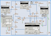
My first attachment.
Shows that we can possibly squeeze out like 6 Watt RMS
with very low distortion, into 8 Ohm speakers.
This is not bad
When we think of 12 Volt supply & that this means Output is at:
- 9,80 Volt peak
- 1,225 Ampere peak ~ 76% of max ( theoretical max = 1.6 A )
Lineup
lineup said:
I have spiced a version of this Hiraga Monstre with transistors that are a bit more 'modern' and can be found to buy.
----------------------
If anyone want me to I post my optimal version of this great
Regards, Lineup
danieljw said:post away lineup, it will be interesting to see your take on Le monstre.
-Dan
Here you are, Daniel.
Some points:
- My spice testing shows, that for 8 Ohm speakers,
the original Hiraga idle current 0.8 Ampere, is a good level
- Mathematically:
0.8 A in push-pull gives max output current = 2x0.8 = 1.6 A
1.6 A x 8 Ohm = peak Voltage out +- 12.8 Volt.
- Which, using a dual 12 VDC supply should be enough.
It should be noted, that using Higher Idle Current bias, than you need,
will most often give more distortion, instead of any improvement.
=========================================
- Transistors in my May 2008 final version ( was doing this one day 1 month ago, 2008-05-31 )
input:
2SK170GR + 2SJ74GR .. IDSS is ~ 4-5 mA
... no problem using them without cascode, as 2SJ74 takes 25 Volt.
- But I added cascode at 6Volt level (half supply) with:
BC560C + BC550C
I do not remember, but probably this gives a bit lower distortion.
I usally avoid cascoding JFETs, unless I see there is some benefit from it.
- Second stage, drivers.
BD139 + BD140
Nothing mysterical. They are the best bang for buck drivers ever made and used in audio.
In this amplifier, Le Monstre, they will fit in very well regarding quality.
- Output transistors.
TIP41 + TIP42
I started out testing with MJ15024 + MJ15025 = TO-3 high power.
But these TIP41/TIP42 OnSemi devices performs better.
Probably because they have higher gain.
Rated 65 Watt and as they will only dissipate like 0.8 x12-15 VDC = 10-12 Watt for Class A,
there is no problem using these easy to find & budget price devices.
They are marketed as:
6 Ampere Complementary Silicon
Plastic Power Transistors
Designed for use in general purpose amplifier and switching
applications.
Datasheet: TIP41/TIP42, PDF
.
My first attachment.Shows that we can possibly squeeze out like 6 Watt RMS
with very low distortion, into 8 Ohm speakers.
This is not bad
When we think of 12 Volt supply & that this means Output is at:
- 9,80 Volt peak
- 1,225 Ampere peak ~ 76% of max ( theoretical max = 1.6 A )
Lineup
Attachments
lineup,
unfortunately, I am less impressed expecting a sonic performance far from the original. Many deteriorating parts, especially the extended Cob of the VAS is extremely muddying. So it`s definitely not an improvement, rather an abuse of the beautiful original idea.
unfortunately, I am less impressed expecting a sonic performance far from the original. Many deteriorating parts, especially the extended Cob of the VAS is extremely muddying. So it`s definitely not an improvement, rather an abuse of the beautiful original idea.
explicitly wrong, not to be used for voltage amplification.BD139 + BD140 Nothing mysterical. They are the best bang for buck drivers ever made and used in audio.
danieljw said:very nice lineup,
interestingly my le monstre puts out approx 6 watts RMS just like the sim
it is surprising how far 6w goes, however i am building the higher power Le class A (upgraded output stage) at the moment.
-Dan.....
The 6 Watt level, as being the limit, when using 0.80 A bias, is not surprise to me.
I have setup many such Class A amplfiers. Of very different circuits.
But most of the time such Class A have the same critical level, at where distortion begins to rise:
.. this is when Peak Output Current is between 75 - 85 % of theoretical Max
In this case was 1.2 A out of 1.6 A ( 2x 0.8A ).
Conclusion:
-------------------------------
When designing Class A amplifier, a good bias target value is:
1.33-1.25 x The max output current the amplifier will deliver
Regarding Lumba Ogir comment.
I don't take it too much serious and I am not very bothered. I have seen it looks like Mr. Ogir likes to be ciritical. In fact, I can not remember any post where Lumba actually has been positive to some other peoples works. There is always some detail he find to bang down into the head of other posters
And I am quite sure Jean Hiraga had been much more positive, if see my circuit. At least if he would have had any points, I think he would have been able to explain himself better.
Lumba is right in one thing.
My version is not an original Hiraga Le Monstre.
In this respect, it is probably like most of those 'Le Monstres' built today.
But my version is an attempt to try to improve on Hiraga's good idea. Using some of today's common and affordable transistors.
This makes my circuit a Lineup Class A, a la Hiraga Monstre.
If this is good or not, is much up to the many readers here to decide.
Lineup
- Home
- Amplifiers
- Solid State
- Hiraga "Le Monstre"