IMHO basically it should be possible to use these modules for a X-amp. Of course Maousse would have to change Rout and feedback resistors. But because of its low supply voltage of +/- 24 VDC the max. obtainable output power will not be very much above 40 watts/8 ohms. This low output power is the reason why I suggested to use MJE340 and MJE350.
GRollins : the UGS modules were for a preamp. With all the experimentations read here and there, the other is now for experimentation purposes. Of course, I assume that some mods would be needed ")
hm4nine : Thanks for the advice. Right now, I just read, not ready for action yet , but I assume that a new PCB would surely be needed.
Regards,
Trung
hm4nine : Thanks for the advice. Right now, I just read, not ready for action yet
, but I assume that a new PCB would surely be needed.Regards,
Trung
Maousse, I suggest you to save at least one pair of your actual UGS-modules and to use them for a preamp. From the second pair you will have to solder out the Toshiba-Fets for your new modules; you know, production is discontinued.
BTW: Is somebody here who knows a source with reasonable prices for those Fets? I would need 10-20 pcs. of each type.
Borbely Audio and Schuro (both Germany) have no more on stock.
BTW: Is somebody here who knows a source with reasonable prices for those Fets? I would need 10-20 pcs. of each type.
Borbely Audio and Schuro (both Germany) have no more on stock.
Hi,
try to mail at dan@djgardner.com
i bought him 6 pairs of these Jfet and prices are "reasonnable) ! But now a lot of people order to him so hurry up !
try to mail at dan@djgardner.com
i bought him 6 pairs of these Jfet and prices are "reasonnable) !
But now a lot of people order to him so hurry up !Maousse said:I already have 4 UGS modules complete and setup
Right now, I'm looking at the amps using UGS as input stage, and/or AlephX... yes yes, the X virus is spreading!
I interpreted this post as meaning the use of a UGS as the front end of an Aleph-X circuit. It seems I misinterpreted things.
I'm all for using a UGS for a preamp feeding an Aleph variant. Sorry for any confusion.
Grey
GRollins said:
I interpreted this post as meaning the use of a UGS as the front end of an Aleph-X circuit. It seems I misinterpreted things.
I'm all for using a UGS for a preamp feeding an Aleph variant. Sorry for any confusion.
Grey
This post was relativ to this other from Cheff :
http://www.diyaudio.com/forums/showthread.php?postid=1167632#post1167632
Marc
Grey,GRollins said:
I interpreted this post as meaning the use of a UGS as the front end of an Aleph-X circuit. It seems I misinterpreted things.
I'm all for using a UGS for a preamp feeding an Aleph variant. Sorry for any confusion.
Grey
You were right, but I'll keep one pair for a preamp.
The other was some spare, but will be diverted to some funny stuff like input stage of a FET amp variant of some kind or another...
so, of course, I agree with hm4nine !
UGS availability
Sorry to jump in on this thread, but does anyone supply a UGS preamp as a finished article or better still as a complete kit.
I've had some success building a UcD based amp, but connecting preassembled modules together is about as far as my skills go.
Building something like a UGS into a UcD based chassis would make an awesome project.
thanks
Re: UGS availability
except NP?
dunno............
it's still copyrighted..........
iwf said:Sorry to jump in on this thread, but does anyone supply a UGS preamp as a finished article or better still as a complete kit.
...................
except NP?
dunno............
it's still copyrighted..........
Excellent stuff! I've been lurking on this thread for quite a while, planning my own version. Now finally I have the prototype built - it's time for me to contribute my first chapter to the 'UGS Adventures' saga...
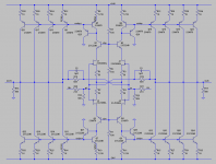
I designed a modified version of Cheff's BJT current-mirror UGS, built the first prototype, and so far have seen absolutely outstanding DC stability from this circuit - far better than any other discrete circuit I've built to date (which is quite a few, although I have some 990 boards sitting here waiting to get built - they might rival the DC performance). More on the circuit performance in a moment, first some details on the circuit:
I had several objectives in mind for my modified version... first, I wanted to use a little better BJT devices than the Zetex parts, which have somewhat low-ish beta and not the best linearity. Three alternatives came to mind: BC550C / BC560C, 2SA1085GR / 2SC1815GR, and 2SA970BL / 2SC2240BL, in increasing order of preference. For my proto, I used the latter, having sufficient stock on hand to build two full units for listening tests - and the A970 definitely has the best linearity at low Vce of the bunch.
Second, I felt that lower distortion might be obtained with careful selection of the Re and Rd resistor values such that the operating Vbe of the mirror output transistors matches the reference transistors (eg. referring to Chaff's UGS_V3a.gif schemo in the first post of this thread, I want the voltage at the emitters of Q7 and Q11 to match as closely as possible). With identical emitter resistors, the Vbe does not match, due to the much higher Vce of the output transistors vs. the reference transistors, which are operating at very low Vce (right down in the 'ugly' part of the curves), and thus take a higher Vbe to reach the same collector current. So, a lower emitter resistor value is needed on the outputs, to pull down a bit more current and increase the Vbe to match the reference Vbe. I can't say for sure if doing this improves the THD much or not since the reference and output transistors are operating in very different regions of their curves, but it was easy to design for, and happily resulted in convenient resistor values. My hope is that with sufficiently linear BJTs, the curves are flat enough down in the 0.7V Vce region to let this happen. This is more of a challenge for PNP devices, which usually show much worse linearity than NPNs - the latter often have ruler-flat curves with a sharp shoulder instead of the broad, soft shoulder and low Early voltage of most PNPs. I also decided to use identical devices for reference and outputs, to help ensure matching (and thus hopefully canceling) distortion products as the Vbe of each varies with the signal. Ideally, we're left only with the perfectly linear characteristic of the emitter resistors dictating the relationship between input and output current. Most of that is just theory / conjecture, and I haven't done (and probably won't do) enough measuring to find out if it's really true or not. If the version I built sounds good (no listening done yet - I just got the circuit powered up for the first time late last night!), I'll probably just start listening to it and happily forget about measurements.
Third, I wanted to test the basic Wilson current mirror connection (transistor bases tied directly to reference transistor's collector - as implemented by Cheff) against the Widlar version, where a third BJT is used to drive the mirror transistor base currents as an emitter follower, having it's base connected to the reference transistor's collector. My thought is that apart from the reduced base-current error, this connection also puts a bit more voltage on the collector of the reference transistor, which should improve the Vbe cancellation a bit by bringing the reference transistor closer to the linear region of the curves. On the downside, I suppose this connection may have the potential to actually decrease sound quality by introducing more complexity in the transfer function, thus giving a more complex distortion signature with more harmonics and so on, despite improved overall linearity.
There is an easy means for quick testing between the two configurations - I put sockets on the board for the Widlar transistors. It is very quick to pull them out and install b-e shorting jumpers in their place. Even easier might be to install 2-pin headers across the b-e junction, which can be shorted with the usual 0.1" jumper blocks. In that case, you'd be left with the parasitic b-c junction capacitance, but otherwise the circuit becomes a Wilson mirror. Speaking of sockets, I didn't want to solder my scant few 2SJ109's in (especially not for a prototype), so I made sockets by cutting up some nice machined-pin DIP sockets. Just trim a few mm off the 4 straight legs to match the length of the bent legs, and they fit perfectly - don't think I'll ever solder any of my precious dual FETs again!
Fourth, and most important, I wanted to lower the output impedance, partly so that I could use the circuit for driving headphones. I have some Cinemag CMOQ-3H units sitting here, and these are a perfect candidate for either 3:1 or 2:1 operation, converting the full balanced output into a single-ended drive for the headphones, with a single point of ground contact at the headphone jack, isolated (no loop) from the main circuit star ground and main output shield / chassis ground on the rear panel. But, this requirement also meant that the circuit needed a beefier output current capability, and a lower output impedance. I'm a big fan of low output Z for preamps and line drivers (tends to eliminate the subjective difference between cables), so getting down below 100 - 200R was a high priority (it's also the reason I will not use this circuit as Cheff does, with attenuator on the output - mine will have a 10K relay / binary stepped attenuator on the intput side). So I used 4 parallel output transistors on each side instead of 1, and then decreased the output load resistors from 1K down to 500R. At 3.75mA each (measured on the proto), that's 15mA of idle current on each side - sufficient to drive a pair of headphones pretty hard, especially through a 2:1 trafo. With feedback applied (OLG about 34dB, CLG = 10dB), the output Z goes down to about 55R, which translates to about 35R on the output side of a 2:1 CMOQ-3H (quadfilar windings, 21.5R DCR each).
For feedback, I set the CL gain at 10dB, using 68K feedback resistors, 21K input, and 50K from each summing node to ground. Mostly, these were just handy values. I'd go lower if I had the right resistor values on hand.
And now the part that I'm most excited about: no caps and no servos for a very simple, JFET-input discrete class-A, balanced SuSy circuit - this is really just killer!
Feels almost like the Holy Grail of audio (OK, I'm exaggerating), but I've searched a long time for a discrete circuit which can perform as well as this. The 990C is one of the only others I know of with DC-couple-able performance. The only thing lacking, in my opinion, is a low output impedance. Normally I aim for <2Ohms on preamp circuits, but I think I can probably live with 55ohms if it really delivers on sound quality, as I expect it will. If I still feel it's too high, I also have the option of dropping it to about 35R using those CMOQ-3H transformers as 2:1 step-down for the line outputs as well. Undecided at this point if I'll do that or not - only the listening tests will tell, but I can easily afford to lose 6-10dB of gain in my system - my current preamp is rarely set above -10dB.
Now, on to the measurements:
Quite simply, the DC offset is stunning for a discrete circuit - better than most IC opamps! I'm running the first proto so far with NO heatsink, so there is no thermal coupling between any of the transistors except of course the dual JFETs, and still the differential offset generally stays under 75uV !!! Since I am running balanced output only, I omitted the common-mode DC offset trimpot. Even so, the common-mode offset I'm seeing is only around 5-10mV.
I used 49R9 & 24R9 source resistors on the JFETs (Dale RN60D's, which are a low noise type - important in this case. If you can afford it, bulk metal foil resistors might do even better here), with a 50R 10-turn Bourns trimpot for differential trim - slightly different from Cheff's values of 22R/47R, but that's what I had available. Either way will work fine. With the 10-turn trimpot, adjusting the offset was pretty easy - I managed to hit a setpoint of about +30uV without much effort, but you can only really tell what your setpoint is based on long-term averaged readings. 1/f noise causes some short-term wander, so if you're seeking perfection, then getting it trimmed out that last little bit is tricky. Usually the output stays within about +/-50uV of the set point anyway, which is easily good enough for just about any practical need. Speaking of 1/f, I left my bench meter running on min/max mode for about 6 hours to see what the largest DC excursions would be over a larger statistical sample (1/f noise, as the name implies, increases in amplitude at lower frequencies, so to see how it really behaves at 0.001Hz etc., you need to measure over a long interval). After 6 hours, the meter had registered maximum excursions of +/-430uV relative to the setpoint, with the inputs shorted together. Keep in mind, this is without any heatsink to provide thermal coupling between the transistors! I was even blowing on one side of the circuit at one point, which seemed to have little effect - maybe 75uV change, but hard to distinguish from the random drift. So, I am very pleased with this. I may forego heatsinks altogether, as none of the components in my version really dissipates enough power to need one.
I also measured the basic THD performance. I'm not well set up to measure balanced signals, so I ended up with some measurement-related noise contamination in my THD+N results (I'm pretty sure it's not related to the circuit's inherent noise characteristics), but the THD results from WaveSpectra are probably fine: 0.0008% THD @ +20dBu output, mostly 3rd harmonic. Similar distortion performance at +10dBu and 0dBu out, then the distortion starts disappearing into the noise floor. 2nd was, unfortunately buried in the rising LF noise floor due to the measurement setup, but somewhere under -110dB. Very good performance on the whole. However, I did see a large number of upper harmonics, out to the 13th or 14th, all at or under -120dB. So that's a little disconcerting. Also interesting was the presence of quite a few even-rder harmonics - 4th, 6th, 10th... this suggests to me that the level of 2nd might have been significant, but just barely hidden in the noise. I have yet to switch over to Wilson config and see if that improves the HD spectrum or not, and IMD test is pending as well. But first I need to resolve the test setup noise issue.
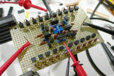
I'll try to post some schemo's and a photo or two later this evening if I can. Very much looking forward to getting the 2nd channel built and listening, but alas I will be travelling on business very soon, so probably won't have time to resume work for about 2 weeks.
Thank you Cheff, here's my small toast to you for building the current-mirror version and posting your results here. You inspired me to try it, and I'm very happy I did. Cheers...
Quite simply, the DC offset is stunning for a discrete circuit - better than most IC opamps! I'm running the first proto so far with NO heatsink, so there is no thermal coupling between any of the transistors except of course the dual JFETs, and still the differential offset generally stays under 75uV !!! Since I am running balanced output only, I omitted the common-mode DC offset trimpot. Even so, the common-mode offset I'm seeing is only around 5-10mV.
I used 49R9 & 24R9 source resistors on the JFETs (Dale RN60D's, which are a low noise type - important in this case. If you can afford it, bulk metal foil resistors might do even better here), with a 50R 10-turn Bourns trimpot for differential trim - slightly different from Cheff's values of 22R/47R, but that's what I had available. Either way will work fine. With the 10-turn trimpot, adjusting the offset was pretty easy - I managed to hit a setpoint of about +30uV without much effort, but you can only really tell what your setpoint is based on long-term averaged readings. 1/f noise causes some short-term wander, so if you're seeking perfection, then getting it trimmed out that last little bit is tricky. Usually the output stays within about +/-50uV of the set point anyway, which is easily good enough for just about any practical need. Speaking of 1/f, I left my bench meter running on min/max mode for about 6 hours to see what the largest DC excursions would be over a larger statistical sample (1/f noise, as the name implies, increases in amplitude at lower frequencies, so to see how it really behaves at 0.001Hz etc., you need to measure over a long interval). After 6 hours, the meter had registered maximum excursions of +/-430uV relative to the setpoint, with the inputs shorted together. Keep in mind, this is without any heatsink to provide thermal coupling between the transistors! I was even blowing on one side of the circuit at one point, which seemed to have little effect - maybe 75uV change, but hard to distinguish from the random drift. So, I am very pleased with this. I may forego heatsinks altogether, as none of the components in my version really dissipates enough power to need one.
I also measured the basic THD performance. I'm not well set up to measure balanced signals, so I ended up with some measurement-related noise contamination in my THD+N results (I'm pretty sure it's not related to the circuit's inherent noise characteristics), but the THD results from WaveSpectra are probably fine: 0.0008% THD @ +20dBu output, mostly 3rd harmonic. Similar distortion performance at +10dBu and 0dBu out, then the distortion starts disappearing into the noise floor. 2nd was, unfortunately buried in the rising LF noise floor due to the measurement setup, but somewhere under -110dB. Very good performance on the whole. However, I did see a large number of upper harmonics, out to the 13th or 14th, all at or under -120dB. So that's a little disconcerting. Also interesting was the presence of quite a few even-rder harmonics - 4th, 6th, 10th... this suggests to me that the level of 2nd might have been significant, but just barely hidden in the noise. I have yet to switch over to Wilson config and see if that improves the HD spectrum or not, and IMD test is pending as well. But first I need to resolve the test setup noise issue.
I'll try to post some schemo's and a photo or two later this evening if I can. Very much looking forward to getting the 2nd channel built and listening, but alas I will be travelling on business very soon, so probably won't have time to resume work for about 2 weeks.
Thank you Cheff, here's my small toast to you for building the current-mirror version and posting your results here. You inspired me to try it, and I'm very happy I did. Cheers...
hifiZen:
very nice! thx for sharing.
glad to see someone carrying on with this.
the adjustments you made as an attempt to improve matching of operating conditions between devices sound reasonable and the resulting dc performance seems quite good.
really looking forward to your listening results.
somehow, i suspect it will not disappoint
i still want to build my folded cascode, open loop version, as well as chef's to compare, but between the day job and honey-do list, who knows when ...
carry on!!!
mlloyd1

- Home
- Amplifiers
- Pass Labs
- UGS adventures