Many year ago I believe that Voyd used three motors (or one motor and two slaves - can't remember now) in a similiar arrangement to that of PT; I've seen it used somewhere else too but can't seem to remember where at the moment.
My issue with the PT arrangement centres on the increased noise that the idler wheel bearings will produce. Whilst it may well solve one issue (if those particular problems exist to any real extent) I can't believe that it doesn't introduce new problems of its own.
My issue with the PT arrangement centres on the increased noise that the idler wheel bearings will produce. Whilst it may well solve one issue (if those particular problems exist to any real extent) I can't believe that it doesn't introduce new problems of its own.
YNWOAN said:Many year ago I believe that Voyd used three motors (or one motor and two slaves - can't remember now) in a similiar arrangement to that of PT; I've seen it used somewhere else too but can't seem to remember where at the moment.
For one:
http://www.audionote.co.uk/products/analogue/tt-3_01.shtml
Hi Casey,
Great project!!!
We seem to be two of a kind")
Do you have some sort of web page or gallery for your projects ?
Here you can see mine, I just build amps instead, but with the same attitude towards building stuff.
www.briangt.com/gallery/magura
Magura
Great project!!!
We seem to be two of a kind
Do you have some sort of web page or gallery for your projects ?
Here you can see mine, I just build amps instead, but with the same attitude towards building stuff.
www.briangt.com/gallery/magura
Magura
Hello Magura,
So it would seem..Fantastic work!! I can see myself spending a fair amount of time drooling over your stuff posted in the gallery you linked.
No gallery for me yet. The table is the first audio project I've started since being out of the hobby for a couple of decades (I have several more on deck). When the table is completed, my son is going help me make a page for it.
Your stuff is a real inspiration..thank you for sharing it.
-Casey
We seem to be two of a kind
So it would seem..Fantastic work!! I can see myself spending a fair amount of time drooling over your stuff posted in the gallery you linked.
No gallery for me yet. The table is the first audio project I've started since being out of the hobby for a couple of decades (I have several more on deck). When the table is completed, my son is going help me make a page for it.
Your stuff is a real inspiration..thank you for sharing it.
-Casey
Turntable:
In all future posts, I will be putting a header like the one above to identify what portion of the project the post pertains to. If I post on more than one area in the same post, I will put up a header separating them. The recent confusion I caused with my air pump motor, as opposed to the turntable motor, made me realize how difficult it's getting for the casual visitor to this thread to follow it. It will only get more confusing in the future when I start on the arm. I had thought about breaking it up the table, arm, and air supply into separate threads, but decided since they are all part of the same system to keep them together.
On with the post...
I checked the motor vibration today, and it showed no sign of improving as I had hoped it would. It seems the deformation of the Sorbothane in the coupler is permanent. Fearing that my be the case when I first suspected it, I had already started plan number...I forget. Of all the couplers I had tried, the spring coupler seemed the quietest when first installed...
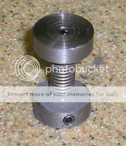
I say “seemed” because the only instrumentation I have to detect minute amounts of physical noise are my senses. Kinda hard to tell the difference between a -90dB and -96dB noise floor unless you have a meter to tell you. The main problem with the spring coupler, besides temporarily hiding my motor alignment problem that eventually roached the first Hurst, was that the vibration of the motor set up a resonance in the spring that caused it to compress itself. It also was a little to compliant in my opinion. I thought it had promise though, so instead of tossing it in the scrap box with the other couplers, I kept track of it. Since my first attempt to address it's problems by wrapping it in a rubber blanket didn't work out, I came up with another approach...
RTV silicon glue. I applied it in three steps. First I compressed it so the coils touched, and laid down about a 1/16 of an inch. When I let it expand, it pulled the silicon in between the coils. I let it sit over night, and when it had cured, laid down another 1/16”. Finally, after it cured again, I filled in any voids, and ran a fillet on the ends. The entire process was done with a 1/8” shaft of a Dremel tool inserted to insure a perfect alignment as the rubber cured. How does it work? Oh...My...God. Not only does the silicon damp the spring resonance, but apparently it helps kill the motor noise at the source. So much so that I can no longer hear any motor hum while it's hanging on the “kinda horn” noise amplifier outside the housing! You can believe I'm grinning like a Cheshire cat now. Whistlin' while I worked, I reassembled the motor, and set it up on table. Fluorescents off, screwdriver pushed in my ear, I went hunting for noise. Side of motor housing..nothing. Top plinth..nothing. Bottom plinth..nothing. The only mechanical noise I could find was on the motor's top plate. The side load on the bushing from the belt increased the top bushing noise from zero to something slightly greater than zero. The top plate acts like a sounding board for any noise the bushing makes. I had actually anticipated this from the beginning..why I cut a recess in the top for a Sorbothane donut. I'm sure once this is in place, this minuscule noise will be gone as well. As for airborne noise at the belt, all but disappeared. There is no longer any belt vibration that I can feel, and the noise level has dropped to the point that all you hear, with your ear practically touching the pulley, is a combination of belt hiss, mixed with a faint bushing noise, and a random static crackle (the hiss may be static as well).
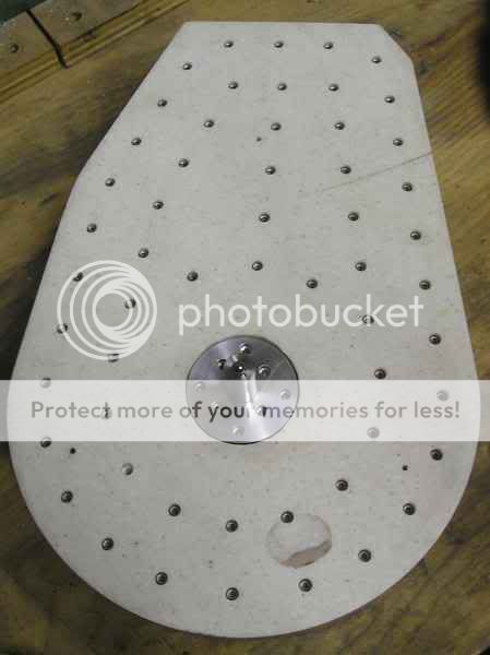
This brings me to a topic I haven't covered yet...static. Running a Mylar belt around an Acrylic platter is a pretty good facsimile of a Van De Graaff generator. This realization is one of the reasons I went with layered lead sheeting in my platter, rather than the more common lead shot. The screws that hold the bearing housing in the platter...
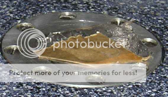
are 3” long and threaded the whole length. These screw through all the lead sheets except the top one (the last layer of lead and Corion were added later),one of which is in the belt groove. I will sink some screws from the top through the first two lead layers, tying them together electrically. I plan to polish the bottom of the bearing housing and have a couple strands of conductor mounted on the plinth running on the polished surface in conductive grease. The screw holding the “brush” on the plinth will connect to the aluminum/lead core of the plinth, and through the core to the feet. The feet connect to the lead filled pods, and through them the core of the bottom plinth. This “circuit” will be connected to ground, effectively (I hope) draining the static charge as it develops.
On a personnel note, on the occasion of breaking 40K views of my little endeavor, I would like to thank all of you who have been following my progress. Our relationship is more symbiotic than you may realize. Watching the view count climb has been an encouragement to me, and on more than one occasion was the little extra push I've needed to keep going during the times when things weren't working out as planned..thank you.
-Casey
In all future posts, I will be putting a header like the one above to identify what portion of the project the post pertains to. If I post on more than one area in the same post, I will put up a header separating them. The recent confusion I caused with my air pump motor, as opposed to the turntable motor, made me realize how difficult it's getting for the casual visitor to this thread to follow it. It will only get more confusing in the future when I start on the arm. I had thought about breaking it up the table, arm, and air supply into separate threads, but decided since they are all part of the same system to keep them together.
On with the post...
I checked the motor vibration today, and it showed no sign of improving as I had hoped it would. It seems the deformation of the Sorbothane in the coupler is permanent. Fearing that my be the case when I first suspected it, I had already started plan number...I forget. Of all the couplers I had tried, the spring coupler seemed the quietest when first installed...
I say “seemed” because the only instrumentation I have to detect minute amounts of physical noise are my senses. Kinda hard to tell the difference between a -90dB and -96dB noise floor unless you have a meter to tell you
. The main problem with the spring coupler, besides temporarily hiding my motor alignment problem that eventually roached the first Hurst, was that the vibration of the motor set up a resonance in the spring that caused it to compress itself. It also was a little to compliant in my opinion. I thought it had promise though, so instead of tossing it in the scrap box with the other couplers, I kept track of it. Since my first attempt to address it's problems by wrapping it in a rubber blanket didn't work out, I came up with another approach...
RTV silicon glue. I applied it in three steps. First I compressed it so the coils touched, and laid down about a 1/16 of an inch. When I let it expand, it pulled the silicon in between the coils. I let it sit over night, and when it had cured, laid down another 1/16”. Finally, after it cured again, I filled in any voids, and ran a fillet on the ends. The entire process was done with a 1/8” shaft of a Dremel tool inserted to insure a perfect alignment as the rubber cured. How does it work? Oh...My...God. Not only does the silicon damp the spring resonance, but apparently it helps kill the motor noise at the source. So much so that I can no longer hear any motor hum while it's hanging on the “kinda horn” noise amplifier outside the housing! You can believe I'm grinning like a Cheshire cat now. Whistlin' while I worked, I reassembled the motor, and set it up on table. Fluorescents off, screwdriver pushed in my ear, I went hunting for noise. Side of motor housing..nothing. Top plinth..nothing. Bottom plinth..nothing
. The only mechanical noise I could find was on the motor's top plate. The side load on the bushing from the belt increased the top bushing noise from zero to something slightly greater than zero. The top plate acts like a sounding board for any noise the bushing makes. I had actually anticipated this from the beginning..why I cut a recess in the top for a Sorbothane donut. I'm sure once this is in place, this minuscule noise will be gone as well. As for airborne noise at the belt, all but disappeared. There is no longer any belt vibration that I can feel, and the noise level has dropped to the point that all you hear, with your ear practically touching the pulley, is a combination of belt hiss, mixed with a faint bushing noise, and a random static crackle (the hiss may be static as well).This brings me to a topic I haven't covered yet...static. Running a Mylar belt around an Acrylic platter is a pretty good facsimile of a Van De Graaff generator. This realization is one of the reasons I went with layered lead sheeting in my platter, rather than the more common lead shot. The screws that hold the bearing housing in the platter...
are 3” long and threaded the whole length. These screw through all the lead sheets except the top one (the last layer of lead and Corion were added later),one of which is in the belt groove. I will sink some screws from the top through the first two lead layers, tying them together electrically. I plan to polish the bottom of the bearing housing and have a couple strands of conductor mounted on the plinth running on the polished surface in conductive grease. The screw holding the “brush” on the plinth will connect to the aluminum/lead core of the plinth, and through the core to the feet. The feet connect to the lead filled pods, and through them the core of the bottom plinth. This “circuit” will be connected to ground, effectively (I hope) draining the static charge as it develops.
On a personnel note, on the occasion of breaking 40K views of my little endeavor, I would like to thank all of you who have been following my progress. Our relationship is more symbiotic than you may realize. Watching the view count climb has been an encouragement to me, and on more than one occasion was the little extra push I've needed to keep going during the times when things weren't working out as planned..thank you.
-Casey
Hi adhoc,
Yes it is
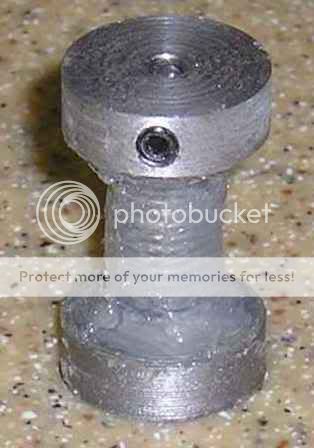
Gee...what makes you think I would have any future problems with my motor?. In a show of faith that this chapter is actually closed, I put Loc-Tite on my set screws. I think I have finally stumbled on the right combo..I still find myself grinning when I think about it.
neutron7-
See...win-win
-Casey
Excellent news Casey!
Yes it is
[now let's hope it holds... ]
Gee...what makes you think I would have any future problems with my motor?
. In a show of faith that this chapter is actually closed, I put Loc-Tite on my set screws. I think I have finally stumbled on the right combo..I still find myself grinning when I think about it.neutron7-
another view. another bit gleaned, another little push for you
See...win-win
-Casey
Running a Mylar belt around an Acrylic platter is a pretty good facsimile of a Van De Graaff generator.
Why is this so? Is the motor shaft not grounded?
pixpop-
Currently the motor isn't grounded, but will be (my test jig is a 2 wire cord and cap). But if it were, and the platter wasn't, that would be your 2 poles. Mylar doesn't conduct, so some charge would remain in the platter.
-Casey
Why is this so? Is the motor shaft not grounded?
Currently the motor isn't grounded, but will be (my test jig is a 2 wire cord and cap). But if it were, and the platter wasn't, that would be your 2 poles. Mylar doesn't conduct, so some charge would remain in the platter.
-Casey
Currently the motor isn't grounded, but will be (my test jig is a 2 wire cord and cap). But if it were, and the platter wasn't, that would be your 2 poles. Mylar doesn't conduct, so some charge would remain in the platter.
Hi Casey
Will Corian hold a static charge? I wouldn't have thought so.
Acrylic, on the other hand...
In any case, you could easily drain it from the system by making sure one of your idler pulleys (belt tensioner) is grounded back to earth.

neutron7-
I could.
Probably..a little anyway.
Jess-
Corion is Acrylic..with some other stuff tossed in. As such...
Well...my tensioner is a pivot on my motor, no idler. In any case, I live in a very arid climate, and I have found static to be very tenacious around here. My approach is probably overkill (big suprise ), but it puts my inner geek at ease.
-Casey
you could use pins like they have in tape decks to discharge the static?
I could.
or would that generate noise somehow?
Probably..a little anyway.
Jess-
Will Corian hold a static charge? I wouldn't have thought so. Acrylic, on the other hand...
Corion is Acrylic..with some other stuff tossed in. As such...
In any case, you could easily drain it from the system by making sure one of your idler pulleys (belt tensioner) is grounded back to earth.
Well...my tensioner is a pivot on my motor, no idler. In any case, I live in a very arid climate, and I have found static to be very tenacious around here. My approach is probably overkill (big suprise
), but it puts my inner geek at ease.-Casey
Turntable:
Noise is like an onion, not only can it make you cry, it has layers on layers
I spent last evening dialing in levels, and tensions to minimize the residual belt noise at the pulley, and to find out how well the motor works once everything was “calibrated”. On the upside this little weeny 2 oz-in torque motor pulls the 20+ Lb. platter up to speed in about 3 revolutions of the platter..simply amazing. The earlier motor took 5-10, and half the time would throw the belt trying. With my experience with the first motor,and expecting the same, I was looking at a “kickstart” setup, but this has turned out to be wholly unnecessary. On the noise front (remember, I'm gilding the Lilly here), the noise level dropped enough, after optimizing the setup, to expose another imperfection..my pulley is off center a few ten thousandths of an inch. Instead of a steady “s-h-h-h-h-h-h” sound of the belt rolling along, I get a “shuh-shuh-shuh” as the belt tension changes on the revolution...again, you have to have the pulley practically in your ear to hear it.
Today's fun and games will be to true up the pulley the same way I trued up my spindle..with it rotating on my mill table while I skin it with the Dremel.
Let the games begin...
-Casey
Turntable:
I trued up the pulley while it was running on the motor with the Dremel on the X-Y table as planned, and the results were as predicted..a substantial lowering of belt noise. When I cut the pulley I had originally intended to do this , so I made it .0015” oversize. But since it seemed to be true, I put it off. Well, it was pretty true, but at a slight angle, so I ended up grinding off .003”. Now I have a pulley .0015” undersized. No biggie since it will be driven by a variable frequency supply.
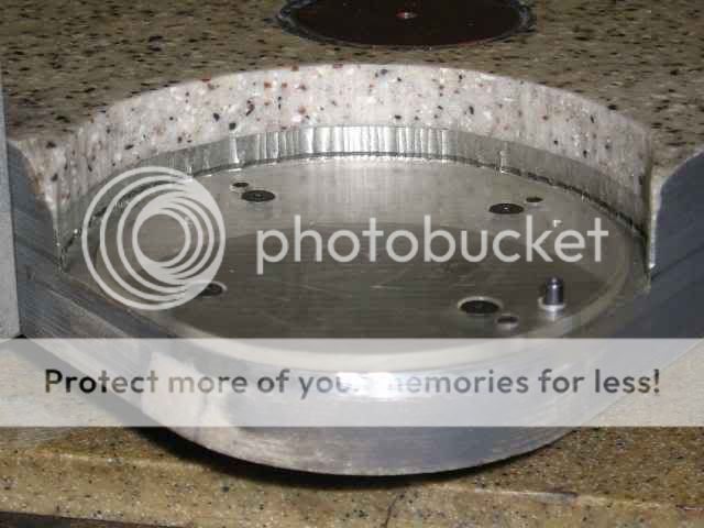
Turning my attention to the top plinth, I took on a chore I had been putting off for a long time. When I had stitched the plinth together with cap screws, I was leaning toward a wood veneer for the finish, and promptly backfilled them in with automotive putty (Bondo). About 2 seconds after I was done, I realized that I had set the plinths acoustic properties, and without listening to determine if my best guess was the right one, as far as screw tension was concerned, made it permanent. This has been continuing to nag at me, so I did something about it..
It seems I really enjoy making work for myself. I spent about 4 hours undoing that unwise move. It was a multi step process getting the screws dug out, while leaving a clean countersink hole. First I drilled down the center of the putty with an undersized drill until I hit the screw. I then sprayed solvent into the hole to loosen the remaing putty, and picked out the hole for the allen wrench. Once I could get the wrench in the screw, I backed it out, and then with the proper sized bit clamped in some vise-grips, “cored” out the hole. Repeat as needed..in this case 56 times. It was worth it. Playing around with screw tension, I am able to make it as dead as mud, or as lively as hardwood. This will allow me some real flexibility when I'm dialing in the arm/table/cartridge.
Since laminating is out, I have decided on a neo-industrial look. I'm going to paint it satin black, and use stainless steel cap screws..the picture in my head tells me it will look bad-a**.
While dinking with belt tracking, I found that for best tracking, the platter had to be taken off of level by adjusting the top plinth feet. Not wanting this (obviously), I fabbed a motor leveler...
I made it out of Plexiglas because it was the only thing I had knocking around the right thickness. The jury is still out on this one, though I'm leaning at tossing it. I found it a major PITA to adjust so that it didn't warp, creating more problems than it solved. I can accomplish the same thing by adjusting the feet on both plinths, so that the platter is level, and the bottom plinth is slightly off level. This would be of little consequence (other than offending my sensibility)since the only functions the bottom plinth performs is holding/isolating the motor, and holding the lead shot for the foot pods (well that, and looking real cool).
Figuring that the table deserved a better belt than the one with the crooked splice, I made another and learned something important in the process. When I ordered the Mylar ribbon to make belts from, I got both silver and red. I decided the silver looked best, so that is what I have been using. Since the new test belt would get used up anyway, I figured I would use the red, saving the silver for later. Even though this one was straight as an arrow, I couldn't get it to track to save my life, and I had to tension the heck out of it in order to not slip instead of pull the platter at start up...adhesion. The silver has aluminum sputtered on one side to give it it's color, the red is infused in the Mylar. This thin aluminum coating provides just enough grip for the pulley profile to keep it centered, and to grab the platter at startup..the straight up Mylar is like a Slip-N-Slide.
Air Supply:
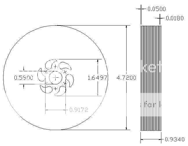
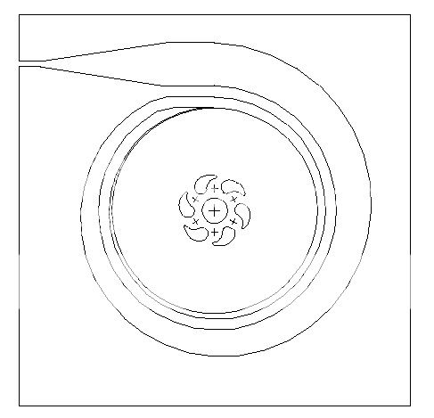
I've more or less finalized my Tesla air pump design using CDROMS as the discs. I'll be using a 1” stack of 14 roms with an initial spacing of .018”...
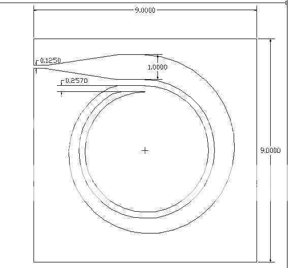
I'll optimize the spacing once it's actually running. The housing is the tricky part. The air exits at a high velocity, and needs to be slowed down before collecting to minimize loss from turbulence. The way to do this is with an “annular diffuser”...
The rate of increase around the discs is .007” every 10 Deg., this is increased to roughly .03” per 10 Deg. on the second trip around, giving an effective outlet of 1”. This is then funneled down to a 1/8 outlet. A very similar concept to the expansion chamber on a 2-cycle engine exhaust. Here is what they look like together...
I really have know idea if this is going to work well enough or not, but I want it to, so I'm building one to see.
-Casey
I trued up the pulley while it was running on the motor with the Dremel on the X-Y table as planned, and the results were as predicted..a substantial lowering of belt noise
. When I cut the pulley I had originally intended to do this , so I made it .0015” oversize. But since it seemed to be true, I put it off. Well, it was pretty true, but at a slight angle, so I ended up grinding off .003”. Now I have a pulley .0015” undersized. No biggie since it will be driven by a variable frequency supply.Turning my attention to the top plinth, I took on a chore I had been putting off for a long time. When I had stitched the plinth together with cap screws, I was leaning toward a wood veneer for the finish, and promptly backfilled them in with automotive putty (Bondo). About 2 seconds after I was done, I realized that I had set the plinths acoustic properties, and without listening to determine if my best guess was the right one, as far as screw tension was concerned, made it permanent. This has been continuing to nag at me, so I did something about it..
An externally hosted image should be here but it was not working when we last tested it.
It seems I really enjoy making work for myself. I spent about 4 hours undoing that unwise move. It was a multi step process getting the screws dug out, while leaving a clean countersink hole. First I drilled down the center of the putty with an undersized drill until I hit the screw. I then sprayed solvent into the hole to loosen the remaing putty, and picked out the hole for the allen wrench. Once I could get the wrench in the screw, I backed it out, and then with the proper sized bit clamped in some vise-grips, “cored” out the hole. Repeat as needed..in this case 56 times. It was worth it. Playing around with screw tension, I am able to make it as dead as mud, or as lively as hardwood. This will allow me some real flexibility when I'm dialing in the arm/table/cartridge.
Since laminating is out, I have decided on a neo-industrial look. I'm going to paint it satin black, and use stainless steel cap screws..the picture in my head tells me it will look bad-a**.
While dinking with belt tracking, I found that for best tracking, the platter had to be taken off of level by adjusting the top plinth feet. Not wanting this (obviously), I fabbed a motor leveler...
An externally hosted image should be here but it was not working when we last tested it.
I made it out of Plexiglas because it was the only thing I had knocking around the right thickness. The jury is still out on this one, though I'm leaning at tossing it. I found it a major PITA to adjust so that it didn't warp, creating more problems than it solved. I can accomplish the same thing by adjusting the feet on both plinths, so that the platter is level, and the bottom plinth is slightly off level. This would be of little consequence (other than offending my sensibility)since the only functions the bottom plinth performs is holding/isolating the motor, and holding the lead shot for the foot pods (well that, and looking real cool
).Figuring that the table deserved a better belt than the one with the crooked splice, I made another and learned something important in the process. When I ordered the Mylar ribbon to make belts from, I got both silver and red. I decided the silver looked best, so that is what I have been using. Since the new test belt would get used up anyway, I figured I would use the red, saving the silver for later. Even though this one was straight as an arrow, I couldn't get it to track to save my life, and I had to tension the heck out of it in order to not slip instead of pull the platter at start up...adhesion. The silver has aluminum sputtered on one side to give it it's color, the red is infused in the Mylar. This thin aluminum coating provides just enough grip for the pulley profile to keep it centered, and to grab the platter at startup..the straight up Mylar is like a Slip-N-Slide.
Air Supply:
I've more or less finalized my Tesla air pump design using CDROMS as the discs. I'll be using a 1” stack of 14 roms with an initial spacing of .018”...
An externally hosted image should be here but it was not working when we last tested it.
I'll optimize the spacing once it's actually running. The housing is the tricky part. The air exits at a high velocity, and needs to be slowed down before collecting to minimize loss from turbulence. The way to do this is with an “annular diffuser”...
An externally hosted image should be here but it was not working when we last tested it.
The rate of increase around the discs is .007” every 10 Deg., this is increased to roughly .03” per 10 Deg. on the second trip around, giving an effective outlet of 1”. This is then funneled down to a 1/8 outlet. A very similar concept to the expansion chamber on a 2-cycle engine exhaust. Here is what they look like together...
An externally hosted image should be here but it was not working when we last tested it.
I really have know idea if this is going to work well enough or not, but I want it to, so I'm building one to see.
-Casey
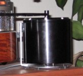
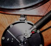
Motor damping/adjustment
Inspired by your project to damp my motor noise. Seen here and the following photo, I made a little platform for the motor and put sorbothane feet on the bottom. I glued aluminum foil to the bottom of the feet so that it will slide easily on the platform. I then added a vertical support with sorbothane against the motor and against the tt. Again, foil on the motor and table surface of the sorbothane, so that I can slide either easily against it. Tension is adjusted by sliding the motor and platform left to right along the edge of the tt. Low tech but works very well and I can hear no noise at all at the speaker.
Side view:
Attachments
- Status
- This old topic is closed. If you want to reopen this topic, contact a moderator using the "Report Post" button.
- Home
- Source & Line
- Analogue Source
- Corian Turntable Fun