

DIY ES9018 DAC + LM4780 AMP Details part 2
Posted 6th January 2015 at 12:29 PM by Maciej Czerwinski
POWER AMPLIFIER:
It works in parallel configuration in order to drive 4 ohm speakers easier. Such configuration has quite low input impedance, around 5kOhm, and low gain of 3.7. This, with the 3x20k input signal resistor divider, gives the maximum output power of only 1W for single sine.
The two pairs of 100k, multi-turn potentiometers set the symmetry of each amplifier. It has to be adjusted manually. In order to do it, you have to supply in-phase (single ended) signal to the input of each amplifier and turn the potentiometers until the signal at the output of each amplifier drops to zero (or rather goes below the noise floor). Unfortunately it also affects the voltage at the amplifier output. There is a lot of trial-and-error work needed to achieve zero signal and zero volts at the output. It is good to do it separately for each of the amplifier from the pair by unsoldering output 0.1 ohm resistors. Signal generator and frequency spectrum meter comes in handy for this task. I simply used my EMU 0202.
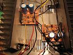
Each (left & right) channel has its own board and an aluminum heatsink. The heatsinks diameters are 165 x 75 x 35 mm (W x H x D), and have 14 fins each.
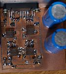
Power amp board top:
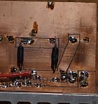
And bottom:
Both boards with heatsinks mounted inside the housing:
It works in parallel configuration in order to drive 4 ohm speakers easier. Such configuration has quite low input impedance, around 5kOhm, and low gain of 3.7. This, with the 3x20k input signal resistor divider, gives the maximum output power of only 1W for single sine.
The two pairs of 100k, multi-turn potentiometers set the symmetry of each amplifier. It has to be adjusted manually. In order to do it, you have to supply in-phase (single ended) signal to the input of each amplifier and turn the potentiometers until the signal at the output of each amplifier drops to zero (or rather goes below the noise floor). Unfortunately it also affects the voltage at the amplifier output. There is a lot of trial-and-error work needed to achieve zero signal and zero volts at the output. It is good to do it separately for each of the amplifier from the pair by unsoldering output 0.1 ohm resistors. Signal generator and frequency spectrum meter comes in handy for this task. I simply used my EMU 0202.
Each (left & right) channel has its own board and an aluminum heatsink. The heatsinks diameters are 165 x 75 x 35 mm (W x H x D), and have 14 fins each.
Power amp board top:

And bottom:

Both boards with heatsinks mounted inside the housing:

Total Comments 0


